This thread has been locked.

If you have a related question, please click the "Ask a related question" button in the top right corner. The newly created question will be automatically linked to this question.

ADS1255 ENOB

Other Parts Discussed in Thread: PGA281, ADS1256, ADCPRO, ADS1255

Hello there,

I'm using an ads1256 converter and a PGA281 front-end configured as Vout = 0.5 * Vin.

Using AdcPro I observe 1bit difference in the ENOB measurement from the following set ups:

- ADS1256 (AIN0 AIN1), no front end AIN0, AIN1 shortcircuited --> 23.8 ENO

- ADS1256 (AIN0 AIN1), PGA281 front end (Vout = Vin * 0.5), PGA281 inputs shortcircuited ---> 22.8 ENOB  

It seems that PGA281, used as attenuator, is introducing noise and is degrading the RMS noise.

I understand that ENOB it's the same because in the second set-up FSR is 20V and not 10V as in the first, but I'm wondering if there is something else..

Regards,

Paolo

  • Hi Paolo,

    Welcome to the TI E2E Forums!

    Adding an amplifier into your circuit will certainly contribute additional noise that can be observed in the ADC results. The amount of contributed noise will depend on the amplifiers noise spectral density curve, the amplifier gain, and the noise bandwidth (usually limited by the ADC's digital filter).

    Regarding the ADCPro ENOB calculation, it doesn't know that you're setting the PGA281 to a gain of 0.5 V/V and is simply calculating ENOB as log2(FSR/Vnoise_rms), where FSR = (4 * VREF / PGAadc). Therefore, I think you're right about the ENOBs being equal due to the difference in FSR.

    Best Regards,
    Chris

  • Hello Chris,

    thank you very much for your comments.

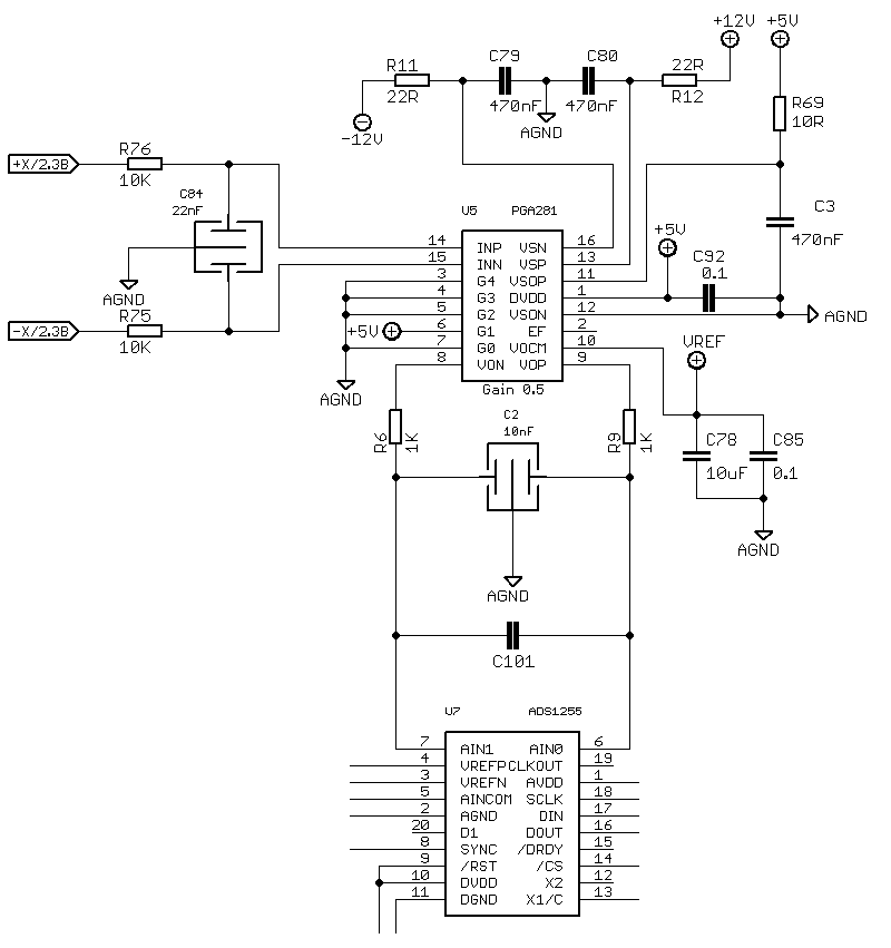
    I have attached a schematic of the board I'm working with (C101 is not populated).

    My problem is, beyond ENOB, the fact that I measure a lower RMS noise level without PGA281 (C101 shorted, and connected to AGND) than what I can measure with PGA281 inputs shorted.

    For example @50Sps in the first situation I get 0.7uV RMS, in the second one I get 2.57uVRMS.

    As you can see in the scheme I put a passive RC low pass filter on the PGA281 inputs and another one on its output as suggested on PGA's datasheet . I used X2Y caps for being very well matched.

    Do you see any improvments on the schematic or do  have any hints I can try to get a better RMS noise with PGA281 inputs shorted together?

    Paolo

  • Hi Paolo,

    Unfortunately, I don't think there is much you can do to improve the RMS noise performance with your current circuit...

    - The PGA281 has a broadband noise density of about 240nVrms/sqrt(Hz)
    - The ADS1255's digital filter, set to 50 SPS, has an effective noise bandwidth of about 80 Hz. (This is the area under the digital filter frequency response plot when configured for 50 SPS).
    - The product of 240nVrms/sqrt(Hz) * sqrt(80 Hz) = 2.14 uVrms
    - This is pretty close to the 2.57uVrms your observing.

    So I think you're observing the PGA281's noise, which is present even with the PGA inputs shorted.


    The only way to improve the noise performance would be to use a lower noise amplifier, or to go without the amplifier and rely on a resistor divider to provide the input signal attenuation. Either way you'll run into some challenges and trade-offs...

    - I'm not aware of too many attenuating PGA's that will provide much better noise performance.
    - Building your own attenuating amplifier with discrete components will not have the same level of resistor matching.
    - Most amplifiers with lower broadband noise will still have a significant 1/f noise - which will provide exactly the same noisy results when used in low bandwidth applications.
    - There are a few amplifiers that with have both low broadband and 1/f noise , but these are usually audio amplifiers which generally have higher offset and offset drift specifications...
    - Using a simple resistor divider will not have as high input impedance and low temperature-coefficient resistors can be expensive.
    - You can only increase the resistor sizes so much (to increase the input impedance) before the resistor thermal noise starts to become a problem (You can only achieve about 100k to 1MOhm input impedance using this method).

    I'm sorry - I wish I could recommend a better solution for you! Let me know if you have any additional questions.

    Best Regards,
    Chris