This thread has been locked.

If you have a related question, please click the "Ask a related question" button in the top right corner. The newly created question will be automatically linked to this question.

Question about ADS1299

Other Parts Discussed in Thread: ADS1299

Hi,

I'm using ADS1299 on my platform. And I cannot read the ID correctly. My steps list below:

(a) Power up my board(BeagleBone Black Board based on AM335X processor)

(b) Initialize and pull-down the START pin, RESET pin, PWDN pin. And delay for a while

(c) Pull up the PWDN pin

(d) Pull up the RESET pin

(e) Delay for at least 1 second

(f) Send command 0x06 to reset

(g) Send command 0x11 to stop continuous reading mode

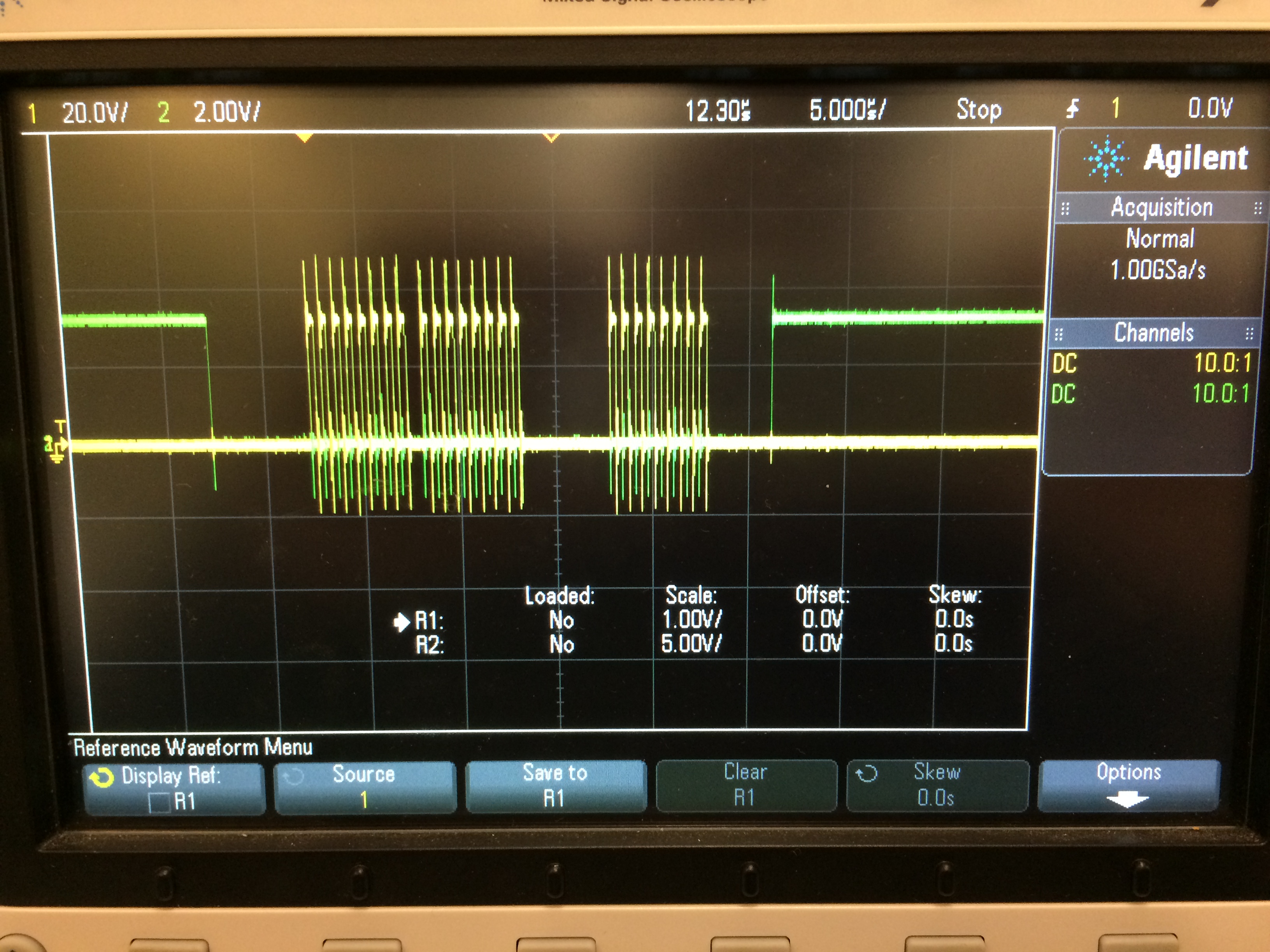
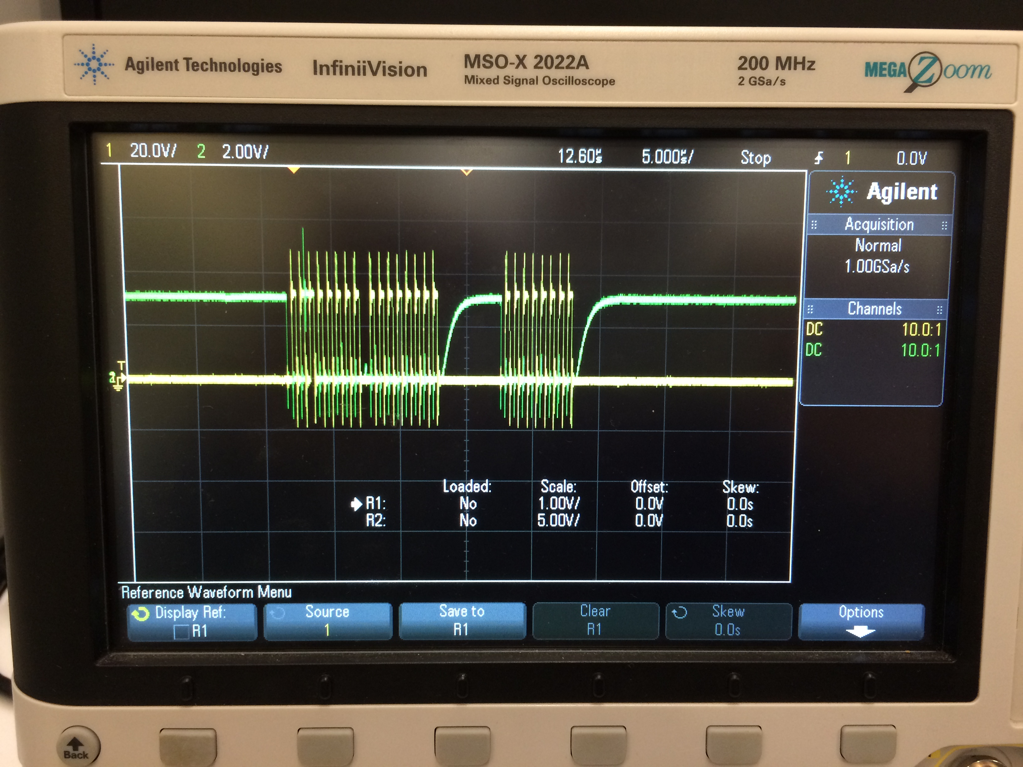
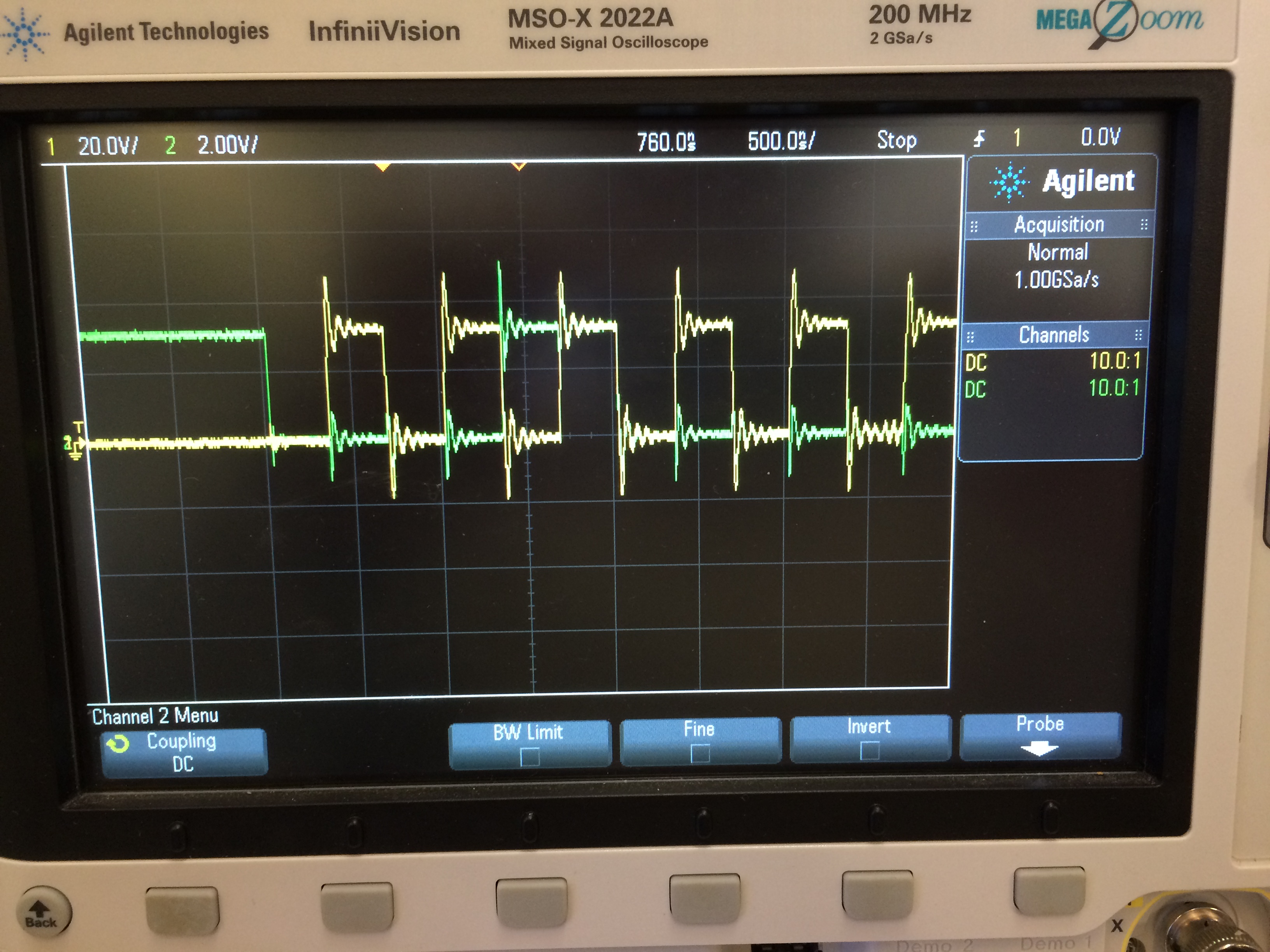
(h) Send command 0x20 0x00, and then read the ID.

The ID read in my application is incorrect, and each time the data is different, like random. I checked the hardware timing and the data I sent is correct.

Could you please give me some hints about this issue?

Thanks a lot.

  • Hey Mian,

    Can you post your schematic and perhaps an oscilloscope screen capture of the read command you perform?

    Regards,
    Brian Pisani
  • Hi,

    The folloing is the timing that I captured. The first is about SPI SCLK and CS, and the second is SPI SCLK and MOSI, and the last is SPI SCLK and MISO:

    I checked the timing, the data sent is 0x20, 0x00, and the data received is always 0x00. About the schematics, I need to confirm with my boss. Could you please tell me whether the power sequence and initialization flow that I listed above is correct?

    And please help to check the timing is correct.

    Thanks a lot.

  • Hey Mian,

    Your timing should be fine as long as those delays that you don't specify meet the requirements given on page 57 of the ADS1299 datasheet. One thing you could do to verify that the device is powered correctly is to pull the start pin high and look for the periodic DRDY signal on the scope. If it never appears, its definitely a power-on issue.

    Looking at the oscilloscope screen shot you gave with SCLK and MOSI, can you confirm that MOSI stays high during the third falling transition of SCLK and satisfies the 11 ns hold time? The interface latches inputs on the falling edge of SCLK so its critical that timing specification is met. For this interface CPOL = 0 and CPHA = 1.

    Regards,
    Brian Pisani
  • Hey Brian,

    If I pull up the start pin, then I can see the periodic DRDY signal every 4ms, which is based on default sampling frequency(250Hz). Another thing is that I also tried to write the register to modify the sampling frequency and it failed all the time because the periodic time is always 4ms.

    I checked the SCLK and MOSI, and it seems OK. Here is the pic for SCLK and MOSI in bigger size below:

    Just hope you could take a look and help me to double check. The command is 0x20.

    And if you have any other suggestions, please tell me.

    Thanks a lot.

    Best Regards,

  • Hey Mian,

    This confirms my original suspicions about the incorrect SPI settings. Refer to page 8 of the ADS1299 datasheet and look at Figure 1. Notice how DIN transitions at or around the rising edge of SCLK and is in a known state at the time that SCLK transitions low. This is critical for the device to have latched the correct value for DIN. In your image, you can see DIN transitioning on the negative edge of SCLK which is not valid for this interface. Change the SPI settings to CPOL = 0 and CPHA = 1 and look at the transaction again.

    Regards,
    Brian Pisani
  • Hi Brian,

    Thank you for your explanation. Now, I changed the SPI mode and can read device ID. And also I can configure sampling frequency.

    Here I have another questions about continuous mode. In my codes, I pull up the start pin and send RDATAC command to ADS1299, then I get the /DRDY signal periodicly (every 4ms by default). And then I read the data from ADS1299, each time I read 27 bytes, which includes 3-bytes status and 24 bytes data from 8 channels. But after a while, somehow, ADS1299 cannot generate /DRDY signal anymore. I measured the /DRDY pin, it maintains high level.

    Do you know why this happened?

    Thanks a lot.


    Best Regards,
  • Hey Mian,

    That is not expected behavior. Probe the power supplies, reset and power down pins, and the start pin to ensure that the device remains in a good power state. What changes between the time that you can read the data as expected and the device stops sending the DRDY signal?

    Regards,
    Brian Pisani