This thread has been locked.

If you have a related question, please click the "Ask a related question" button in the top right corner. The newly created question will be automatically linked to this question.

DAC3482EVM Software Control

Other Parts Discussed in Thread: CDCE62005

Hello

I use the DAC3284 EVM with the DAC348x GUI Version 3.8 on Win7.
I use the internal clock an have a DACCLK of 75MHz in the test.

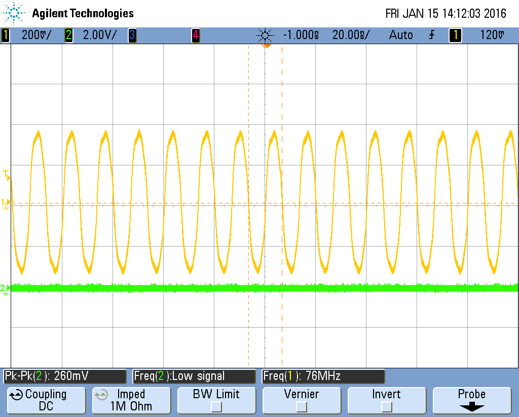
I can adjust some parameters of the DAC in the Digital Card, e.g. the Interpolation and the output signal reacts like i expect.

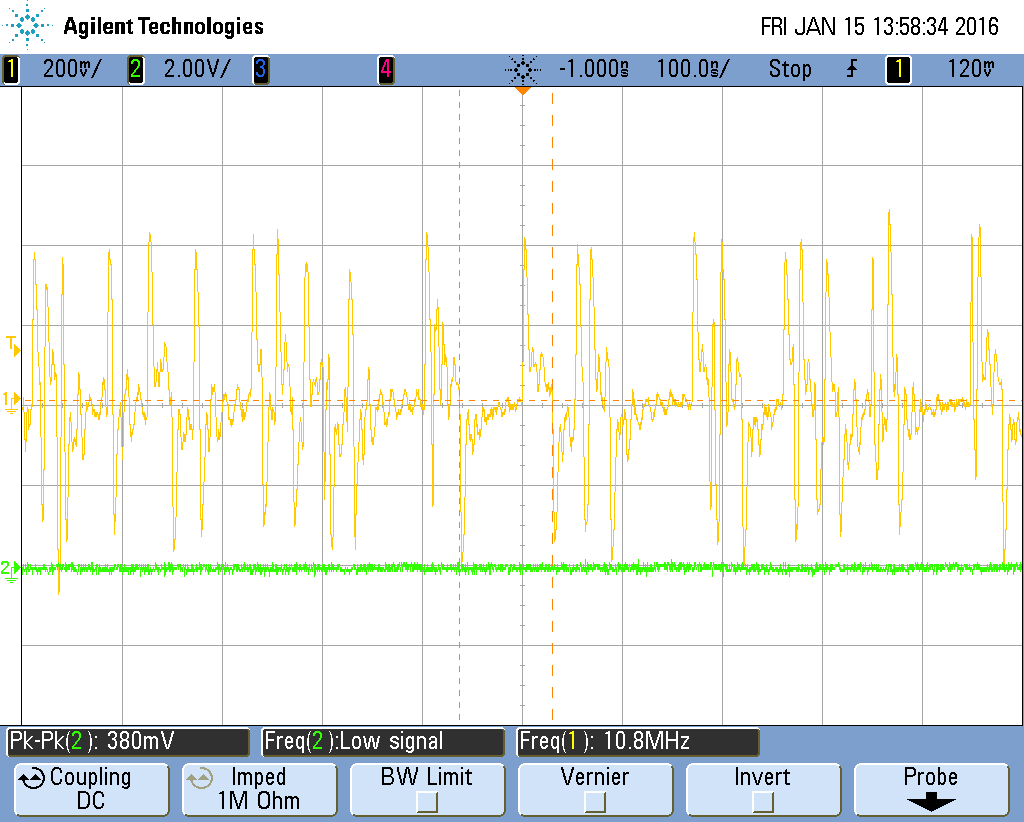
But when I press the "Send All" Button or do changes in the CDCEC62005Control Card, the output is going off, and the internal clock I use is off, too.

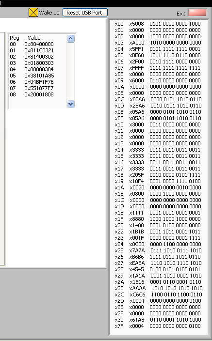
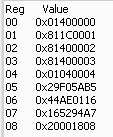
The CDCE registers are unchanged since power-up.

Have I wrong adjustments of the CDCE? Or what else could be a reason for that behaviour?

Thanks

  • Hi,

    It is possible that you used the DAC output shut-off protection feature on the setup. It shuts off DAC automatically upon detection of clock interruption.
    www.ti.com/.../slaa585

    I am not sure your definition of internal clock. Please advise. The CDCE62005 should continue to work unless your setting involves toggling the "wake up" feature, which re-calibrates the VCO. Please also check with the clocking team on the clocks forum for further CDCE62005 support.

    -Kang
  • Hello

    I use the clock generated by CDCE62005 (DACCLK). CDCE62005 use the on board reference clock from U17 (SEC_REF)  (no external reference) 

    This clock is going out when I click the send all button. Also the FPGA_CLOCKOUTP/N from CDCE.

    DACCLK is not at zero when the error occures. See Channel 1 of the scope. First picture is before I do changes in the DAC348x Software Control, second picture after.

    The clk-Signal from U17 (SEC_REF+/-) is still there.

    Does the DAC348x Software execute a VCO Calibration?

    Thanks

  • Michaela,

    The CDCE62005 question is best answered on the clock forum. I can only recommend that you set up the CDCE62005 first through "send all" during the EVM initialization/power before starting the DAC data transmission. This is what we recommend on the datasheet of the DAC348x, too. 

     Digging through my email, I found the following behavior of CDCE62005 when configured with the DAC348x software:

    The CDC output will turn off when the CDC LE transitions to high for about 1.6 usec.  This will happen no matter which register is programmed or whether the register values are actually changing.  

    As a interim solution to the problem we have modified the GUI so that it will not write to the CDC on every iteration.  Now it will write to the CDC only when on the CDC tab *and* a register is modified, or on the first iteration, or when the user selects “Send All”.  For the most part this will eliminate the problem during normal usage except when the user selects “Send All”.  This will cause the issue to happen and will require the user to toggle Sif-Sync to recover. 

    We noticed that that moment CDCE62005 LE transition to low, the clock should recover. The clocking forum should be able to help you if you are designing the CDCE62005 on your PCB.

    -Kang

  • Thank you, I fixed the problem. It works if I always set the CDCE and DAC first and finally do the FPGA configuration.

    Now I want to convert a single pattern.

    I see a delay time of 180ns between putting data and sync to the DAC inputs and the DAC output reaction.

    I have a 250MHz DATACLK and a 500 MHz DACCLK.

    I don’t use the DAC FIFO, PLL or filter.

    I found a propagation delay about 2ns in the DAC data sheet for this configuration. I verified that the 1st Data value is at the DAC input simultaneously with the sync signal. So the delay causes not from the FPGA.

    Can you see a possibility where this delay can come from?

    thank you

    Michaela

  • Michaela,

    The propogation delay is defined as the time for the signal to cross from the digital core to the DAC analog core. You will also need to account for digital latency specification as well. Multiple the number of clock cycles by your DAC sampling time to get the result per the mode that you are using.

  • The DACCLK is 500MHz, so it is a delay about 90 DACCLK cycles. The Mixer is disabled, also the QMC and Inverse sinx/x filter.
    Is there a digital latency by bypassing the FIFO?
  • Hello Michaela

    Bypassing the FIFO only reduces the digital latency. There are still latencies from various DSP blocks such as FIR interpolators, QMC, and sinc filters.

    -Kang

  • Hello Kang

    in the DAC EVM Software GUI  I turned off all digital features. Is it possible to say a value or a range for the propagation delay in this case?

    thank you

    Michaela