This thread has been locked.

If you have a related question, please click the "Ask a related question" button in the top right corner. The newly created question will be automatically linked to this question.

ADS1247 Drift

Other Parts Discussed in Thread: ADS1247

Hello,

I would like to consult on how long-term stability and temperature characteristics of the system designed TIDU145 document?

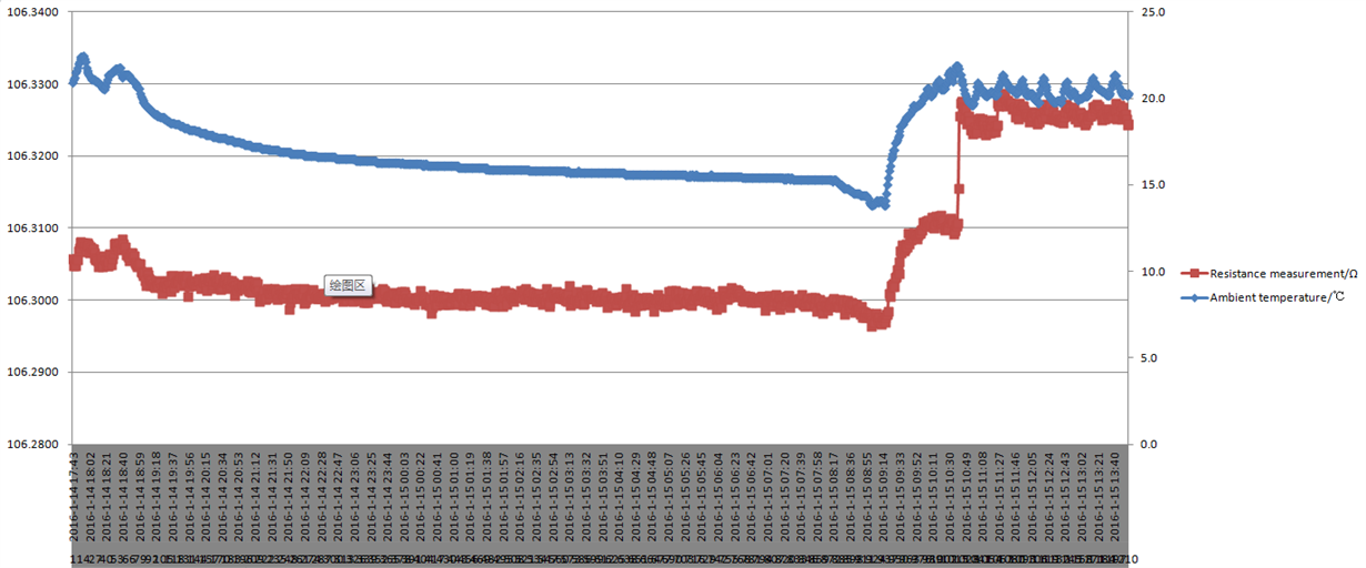
I made reference to TIDU145 document with a few 3-wire PT100 acquisition board, and PCB design and material selection are identical and documents. The input of the access system is a high-precision resistance box, the resistance box Overall accuracy of 0.01% (at 20 ± 5 when). After testing the resistance box fixed in 107.000Ω, running on the system 20 hours after electricity was found a larger difference before and after the resistance value of the system output obtained. PCB relations in the ambient temperature and output values as shown below. Will this situation is still a problem on my operation of the unique design it?

  • Pei,


    In looking at your data, it looks like you are close to the error of the precision resistor for the majority of your readings. It looks like you have a change of about 0.01 Ohms (which is 0.01% of 100) from the beginning of the readings to about the 10:49 time stamp. At that point there is a quick jump in the readings.

    I'll go through a couple of possible sources of the error and you can comment with a post back.

    For the general drift (the first section, without the jump in data), there are several sources that may be contributing to the resistance error even if they are small. First, as you mention there is the precision resistance box. which does have an accuracy of 0.01% from 20±5C.

    However you also need to account for the drift of the reference resistor. If you have the RG2012-L series, then the resistance temperature coefficient is 2ppm/C but for the V series then this is 5ppm/C. For 5ppm/C, this becomes about 0.005% for a 10C span. Note that I think this is a typical value, because Susumu does not list this as a max specification.

    Also, you can look at the typical characteristics curves for the gain error versus temperature. I'm not sure what setting you are using, but it's likely that this too is in the range of 0.005% for a 10C span. Note that the gain error of the ADC is typically 0.005% with a max listing of 0.02%.

    One other specification that you need to consider is that the offset has a drift contribution as well. Again, I'm not sure what your configuration setting is, but it may be adding error. It varies depending on the PGA gain of the ADC.

    The last thing I'd like to address is the jump in code that your are seeing at the 10:49 time stamp. I'm not sure what that is. It looks like a very large offset. I would start by finding out how much that is, by calculating the equivalent voltage change that you are seeing.

    I think this might be an effect of EMI around your board. It seems to start up in the morning, and then there is varying ambient temperature afterward. It could be that this is line cycle interference, or noise associated with lighting. I would run this for a longer period of time, just to see if this starts in the morning and ends every evening. It's likely this is something happening in local environment.

    It might help to build a metal enclosure to shield the EMI from the board. Even if you can't use one in your final product, it may help to test to see if this is the source of the offset.


    Joseph Wu
  • Joseph,
    Thank you very much for your patience to answer. At the same time very sorry so long didn't reply, I'm on vacation, going to the end of February to continue this work.
    The setting i'm using just like Table 7. in the TIDU145 document,my code is:
    ADS1247_RESET();
    ADS1247_WREG(ADS_REG_MUX0,0x0A);//配置AD的正输入端为AIN1,负输入端为AIN2
    Delay1( 2500 );//写MUX0寄存器需要0.513ms的延时,这里延时0.9ms
    ADS1247_WREG(ADS_REG_IDAC1,0x30);//配置电流源输出管脚:AIN0、AIN3
    ADS1247_WREG(ADS_REG_IDAC0,0x93);//电流源输出:250μA
    ADS1247_WREG(ADS_REG_MUX1,0x20);//内部基准电压always on
    Delay1( 2500 );
    ADS1247_WREG(ADS_REG_SYS0,0x72);//PGA=128,20SPS

    Pei Huang
  • Pei,


    I don't see anything different wrong in the register setup. It is unlikely the problem would be something there.

    I think the drift you are seeing may be in the choice in components. If you are following TIDU145, it does require that precision resistors are used. For example the resistor used for RZERO must be extremely precise and low drift. What make and manufacturer did you use for this resistor? If this resistor value changes over temperature, then it represents an error in the measurement. For your setup, the error is also gained up to 128.e

    The resistors used for input and reference filtering might also be a factor. If these resistors are large, then the input bias current reacting with the filter resistors may also contribute an error. I'm not sure if this is what you are seeing, but you can remove the filter resistors and replace them with resistors that are 10x smaller to see if these contribute some drift error.

    Again, this resistive drift does not explain the large change where the measurement takes a jump up in the time plot you provided. I still think this might be some sort of EMI or other environmental issue. As I mentioned in the previous post, I'd try taking measurements over a longer time period to see if it occurs each day. As a test, I'd also check if keeping the board in some sort of metal enclosure will reduce this effect by shielding it from EMI.


    Joseph Wu