This thread has been locked.

If you have a related question, please click the "Ask a related question" button in the top right corner. The newly created question will be automatically linked to this question.

ads1292 spi faults out

Other Parts Discussed in Thread: ADS1292, ADS1192

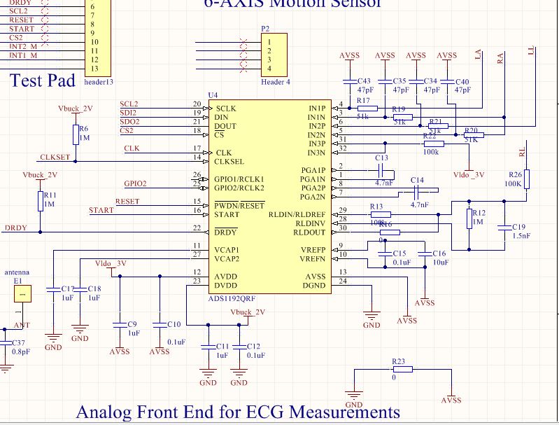
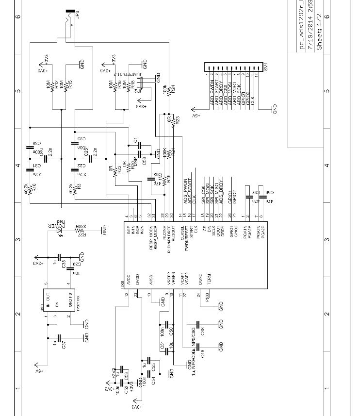
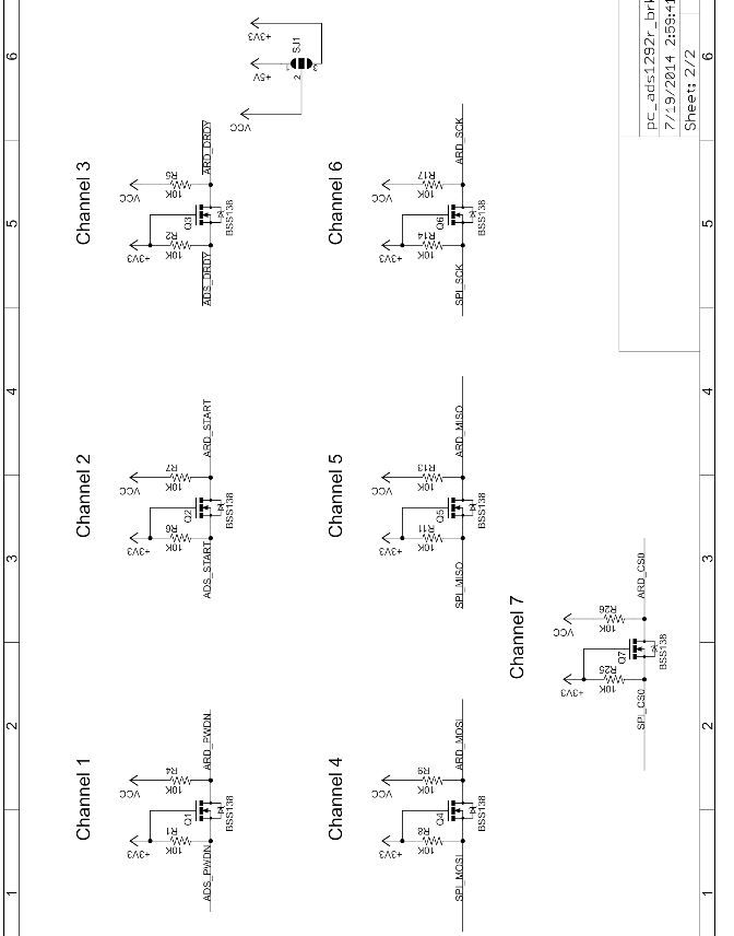
i use nrf52 DK as master and configure ads1292 breakout as slave. . I write the sample spi code  to read the value of the specific register in the ads1292. what happen is that the CS ,SCL,MOSI signal are all correct, but the MISO signal is always wrong.

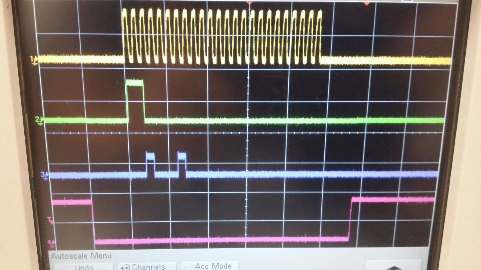
yellow color is sclk,green color is miso, blue one is mosi,pink one is cs. no matter what register i read, the green signal (miso)is always like that. I attached my code as follow。


#include <stdio.h>
#include <stdbool.h>
#include "app_error.h"
#include "app_util_platform.h"
#include "nrf_delay.h"
#include "bsp.h"
#include "app_timer.h"
#include "nrf_drv_spi.h"
#include "nordic_common.h"
#include "nrf_drv_gpiote.h"


#define WRITE_BIT             0x40
#define READ_BIT              0x20
#define APP_TIMER_PRESCALER      0                      /**< Value of the RTC1 PRESCALER register. */
#define APP_TIMER_MAX_TIMERS     BSP_APP_TIMERS_NUMBER  /**< Maximum number of simultaneously created timers. */
#define APP_TIMER_OP_QUEUE_SIZE  2                      /**< Size of timer operation queues. */

#define DELAY_MS                 1000                /**< Timer Delay in milli-seconds. */

#define TX_RX_BUF_LENGTH         2                /**< SPI transaction buffer length. */

#if (SPI0_ENABLED == 1)
    static const nrf_drv_spi_t m_spi_master = NRF_DRV_SPI_INSTANCE(0);
#elif (SPI1_ENABLED == 1)
    static const nrf_drv_spi_t m_spi_master = NRF_DRV_SPI_INSTANCE(1);
#elif (SPI2_ENABLED == 1)
    static const nrf_drv_spi_t m_spi_master = NRF_DRV_SPI_INSTANCE(2);
#else
    #error "No SPI enabled."
#endif

// Data buffers.
static uint8_t m_tx_data[TX_RX_BUF_LENGTH] = {0}; /**< A buffer with data to transfer. */
static uint8_t m_rx_data[TX_RX_BUF_LENGTH] = {0}; /**< A buffer for incoming data. */

static volatile bool m_transfer_completed = true; /**< A flag to inform about completed transfer. */


void app_error_handler(uint32_t error_code, uint32_t line_num, const uint8_t * p_file_name)
{
    UNUSED_VARIABLE(bsp_indication_set(BSP_INDICATE_FATAL_ERROR));

    for (;;)
    {
        // No implementation needed.
    }
}


static void spi_master_event_handler(nrf_drv_spi_event_t event)
{
    uint32_t err_code = NRF_SUCCESS;
   // bool result = false;

    switch (event)
    {
        case NRF_DRV_SPI_EVENT_DONE:
            // Check if data are valid.
          //  result = buf_check(m_rx_data, TX_RX_BUF_LENGTH);
          //  APP_ERROR_CHECK_BOOL(result);

            err_code = bsp_indication_set(BSP_INDICATE_RCV_OK);
            APP_ERROR_CHECK(err_code);

            // Inform application that transfer is completed.
            m_transfer_completed = true;
            break;

        default:
            // No implementation needed.
            break;
    }
}


static void spi_send_recv(uint8_t * const p_tx_data,
                          uint8_t * const p_rx_data,
                          const uint16_t  len)
{
    // Initalize buffers.
   // init_buffers(p_tx_data, p_rx_data, len);

    // Start transfer.
    uint32_t err_code = nrf_drv_spi_transfer(&m_spi_master,
        p_tx_data, len, p_rx_data, len);
    APP_ERROR_CHECK(err_code);
    nrf_delay_ms(10);
}


void bsp_configuration()
{
    uint32_t err_code = NRF_SUCCESS;

    NRF_CLOCK->LFCLKSRC            = (CLOCK_LFCLKSRC_SRC_Xtal << CLOCK_LFCLKSRC_SRC_Pos);
    NRF_CLOCK->EVENTS_LFCLKSTARTED = 0;
    NRF_CLOCK->TASKS_LFCLKSTART    = 1;

    while (NRF_CLOCK->EVENTS_LFCLKSTARTED == 0)
    {
        // Do nothing.
    }

    APP_TIMER_INIT(APP_TIMER_PRESCALER, APP_TIMER_MAX_TIMERS, APP_TIMER_OP_QUEUE_SIZE, NULL);
        
    err_code = bsp_init(BSP_INIT_LED, APP_TIMER_TICKS(100, APP_TIMER_PRESCALER), NULL);
    APP_ERROR_CHECK(err_code);
}


//-----------------------------spi functions----------------------------------
void SPIWriteReg(uint8_t addr, uint8_t value)
{
	  uint8_t temp[2];
    uint8_t temp_rec[2]={0};

    temp[0] = addr | WRITE_BIT;
		temp[1] = value;

    //nrf_drv_gpiote_out_clear(22);		
		spi_send_recv(temp, temp_rec, 2);


		if (m_transfer_completed){
			m_transfer_completed=false;
			nrf_delay_ms(1);
		  //nrf_drv_gpiote_out_set(22);
		}
		
		nrf_delay_ms(1);
	
}

uint8_t SPIReadReg(uint8_t addr)
{
	  uint8_t temp[3];
	  uint8_t temp_rec[3]={0};
	
	  temp[0] = addr | READ_BIT ;
	  temp[1] = 0x00;
		temp[2] = 0x00;
		
		//nrf_drv_gpiote_out_clear(22);
		spi_send_recv(temp, temp_rec, 3);
	  
		
	  if (m_transfer_completed){
//			printf("read_finally\n");
			m_transfer_completed=false;
			nrf_delay_ms(1);
		 // nrf_drv_gpiote_out_set(22);
		}
		
		nrf_delay_ms(1);
		
		return temp_rec[2];
}
void  Disablestart()
{
	nrf_drv_gpiote_out_clear(28);
	nrf_delay_ms(1);
}
void  Enablestart()
{
	nrf_drv_gpiote_out_set(28);
	nrf_delay_ms(1);
}
void reset()
{
	nrf_drv_gpiote_out_set(29);
	nrf_delay_ms(10);
	nrf_drv_gpiote_out_clear(29);
	nrf_delay_ms(10);	
	nrf_drv_gpiote_out_set(29);
	nrf_delay_ms(10);
}

int main(void)
{
	
	uint8_t aa=0x01;
	//	nrf_gpio_cfg_output(30);   //DRDY
	 // nrf_gpio_cfg_output(29);  //PWDN
	 // nrf_gpio_cfg_output(28);  //START


  //  nrf_drv_gpiote_out_set(22);   //This should assert the CS for the SPI peripheral
	    
    	  
 		//nrf_delay_ms(1);
    // Setup bsp module.
    bsp_configuration();
	 

    nrf_drv_spi_config_t const config =
    {
        #if (SPI0_ENABLED == 1)
            .sck_pin  = SPIM0_SCK_PIN,
            .mosi_pin = SPIM0_MOSI_PIN,
            .miso_pin = SPIM0_MISO_PIN,
            .ss_pin   = SPIM0_SS_PIN,
        #elif (SPI1_ENABLED == 1)
            .sck_pin  = SPIM1_SCK_PIN,
            .mosi_pin = SPIM1_MOSI_PIN,
            .miso_pin = SPIM1_MISO_PIN,
            .ss_pin   = SPIM1_SS_PIN,
        #elif (SPI2_ENABLED == 1)
            .sck_pin  = SPIM2_SCK_PIN,
            .mosi_pin = SPIM2_MOSI_PIN,
            .miso_pin = SPIM2_MISO_PIN,
            .ss_pin   = SPIM2_SS_PIN,
        #endif
        .irq_priority = APP_IRQ_PRIORITY_LOW,
        .orc          = 0xCC,
        .frequency    = NRF_DRV_SPI_FREQ_1M,
        .mode         = NRF_DRV_SPI_MODE_1,
        .bit_order    = NRF_DRV_SPI_BIT_ORDER_MSB_FIRST,

    };
    ret_code_t err_code = nrf_drv_spi_init(&m_spi_master, &config, spi_master_event_handler);
    APP_ERROR_CHECK(err_code);
		
		//SPIWriteReg(0x02,0x11);
	while(1)
	{		
    
     aa=SPIReadReg(0x02);
	}
}


  • Hey xin,

    Have you sent the SDATAC command before reading the register?

    Regards,
    Brian Pisani
  • Thank you, Brian.

    I have solved the problem which ia mainly due to wrong initialization of SPI (wrong clock trigger mode)

    now i successfully achieved spi read and write function in ads1292 breakout board.  actually, I used the ads1292 breakout to verify the spi testing code.

     as you know, previously i designed an ECG device with ads1192 chip ( i had asked for your help during the design :)) . since ads1192 is quite similar with ads1292,i want to use the spi testing code to check whether the design chip(ads1192) can work or not.  However when i ran the same testing code in ads1192,  it seems not work properly.  when i test spi read from register function, the received value is alway fixed no matter what register i access to. 

    the code is roughly like that 

    .frequency = NRF_DRV_SPI_FREQ_2M,  //set frequency as 2M
    .mode = NRF_DRV_SPI_MODE_1,            // SCK active high, sample on trailing edge of clock
    .bit_order = NRF_DRV_SPI_BIT_ORDER_MSB_FIRST,   // Most significant bit shifted out first.


    uint8_t temp[3];  // Din opcode
    uint8_t temp_rec[3]={0};  // Dout data

    temp[0] = 0x02 | 0x20 ;     // read the reigister with address 0x01
    temp[1] = 0x00;               // read one register
    temp[2] = 0x00;             


    nrf_drv_gpiote_out_clear(30);    //set cs low
    spi_send_recv(temp, temp_rec, 3);   //spi date transfer

    if (m_transfer_completed){

    m_transfer_completed=false;   // spi off
    nrf_delay_ms(1);
     nrf_drv_gpiote_out_set(30);   //   set cs high
    }

    nrf_delay_ms(1);

    return temp_rec[2];       //return the third byte of Dout

    additionally, in my design the ,START AND RESET pin are connected to mcu directly without pull up network. In the code, i  set the START high. will that affect the spi read from register function ?

  • Hey xin,

    Are there any differences in the hardware setup between the ADS1292 board and the ADS1192 board? Did you simply depopulate the first device and solder the second? There should not be a problem with tying the START and RESET pins to the MCU as long as the correct startup procedure is followed.

    Regards,
    Brian Pisani
  • Thank you, Brian.

    The ads1292 board are bought online which is mainly used to test the spi code. The ads1192 board is designed by me. I connected the ads1192 board with some MCU development kit board.  since those two chip are highly similar, i use the same code to test it.  so i have some questions about  the startup procedure of ads1192.

    1>   is this spi initialization correct for ads1192

     .frequency = NRF_DRV_SPI_FREQ_2M,    //set frequency as 2M
    .mode = NRF_DRV_SPI_MODE_1,            // SCK active high, sample on trailing edge of clock
    .bit_order = NRF_DRV_SPI_BIT_ORDER_MSB_FIRST,   // Most significant bit shifted out first.

    2> when i just perform register read function , is it necessary to send some command like RDATAC, RDATA or START first or i only need send RREG command?

    Thank you again 

  • Hey xin,

    You will need to send the SDATAC command before reading registers.

    Brian
  • Hi brian 

    Thank you very much. it works on ads1292 board after i added SDATAC command. however, when i run the same code on ads1192 board designed by me , it still faults out. i think ads1292 is quite similar with ads1192. is that fine to use same code for both ads1292 and ads1192?(the code only work for register read)

    the ads1192 schematic is like that

    the ads1292 schematic is the following:


  • Xin,

    Are the interface connectors connected in the exact same way as with the ADS1292? Have you verified the SPI transactions on the current board?

    Regards,
    Brian Pisani
  • Hi Brian:


    Thank you for your reply, I have check both ads1292 and ads1192 schematic. most of the connections are same, the most different part is that the pull up network are added to the spi(PWDN,MOSI,MISO,START,SCL, DRDY) interface on ads1292 borad. on ads1192 board, i didn't add those pull up network and  just directly connect the spi pins to mcu.

    the pull-up network is like this

    And i have verified the spi transactions on both ads1292 and ads1192 board. just like i said, I use the same code to run on those two boards. only ads1292 board that can work.(write value to register of ads1292 and read it ).  for ads1192 board, it can't work(can't be written or read).

      1. theoretically, is it correct to run the same code on both board based on those situation? 

      2. Does the pull up/pull down network really affect the spi or should i modify the code due to those pull up or pull down network.

    reaaaaaaaaaaaaally thank you ,Brian. You help me a lot!!

  • Hey xin,

    1. For reading/writing registers, yes. Retrieving data would be different, though, since the ADS1192 outputs only 16 bit data. In your case, I'm looking for differences in the hardware that could affect how things work.

    2. Maybe. I would try checking the interface on the device side of the pull-up network and make sure everything looks like it should.

    I notice you are using a 2 V buck output to power the digital core of the ADS1192. Check to make sure that voltage never dips below 1.7 V. If it does, the part could be powering down. I would also advise you check to see if the device is powering down by looking at the DRDY signal. If it is coming at the default data rate, then you can be sure the digital core is powered correctly.

    Regards,
    Brian Pisani