This thread has been locked.

If you have a related question, please click the "Ask a related question" button in the top right corner. The newly created question will be automatically linked to this question.

ADS1248 Architecture : internal feedback

Other Parts Discussed in Thread: ADS1248, OPA333, INA333

Hi,

I would like to ask you about the architecture of ADS1248.

Does ADS1248 employ a "feedback" signal processing to reduce the output errors?

A Feedback means that the output is feedbacked internaly to input to compare,  like "OPamp feedback".

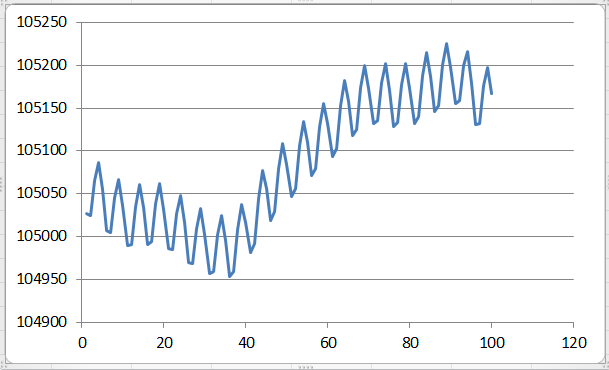
Because one customer has observed following data  which changes slowly and periodically.(about 10Sec/cycle)

This data is temperature data of "Thermocouple".

The customer is concerning that this data changing is due to ADS1248 architecture.

But I am thinking that seems to be due to "environmental issue of measurement"...

I would like to ask you to give me any advice about this.

Thank you in advance.

Best Regards,

  • Takumi-san,


    The ADS1248 does not employ a feedback structure as you are describing. The way that the offset is reduced in this device is a front end chopping (the graph does not look like any chopping effect). I agree with you that this looks like it is some sort of environmental measurement issue.

    How large is this error that they see? For the plot, can they provide the raw data? What is the time scale of the graph? I'd also like to know the configuration of the device (PGA gain, data rate, what reference they use, and the schematic). This does look like some sort of 1/f noise, but I need to know more about the customer's circuit.


    Joseph Wu
  • Joseph-san,

    Thank you for your prompt reply!

    Can I understand that the AFE of ADS1248 employs "chopping stabilized" (zero-drift) amp like OPA333?

    About the more detail information, I will ask the customer to provide.
    If I can succeed to get, let me inform you.

    Best Regards,
  • Takumi-san,


    The ADS1248 is similar to the INA333 (instead of the OPA333).

    If your customer comes back with more information, please feel free to post back their response with whatever data they provide.


    Joseph Wu
  • Thank you for your reply, Joseph-san,

    I understood.

    Regards,

  • Takumi-san,


    I've had a chance to look through the data that you sent me and it looks like there's a variance of about ±0.4% over the course of about 3 hours.

    My guess would be this is some sort of temperature drift over that amount of time, but I'd need more information about the circuit, what they are measuring, and the setup of their system. If it is some sort of temperature drift, it might help to have a some enclosure around it to help remove temperature fluctuations. If the enclosure is metal, then it might also help with EMI as well.

    If this is a thermocouple measurement, how are they generating the bias? Do they use the voltage bias in the mux? Do they use biasing resistors? Since they are likely to be in high gain, it's important to make sure some of the parasitic errors are reduced. If they have large filter resistors, this resistance can react with the input current to give an error. If the resistors drift, it may cause some effect like this.

    Regardless, I'm only guessing about the customer's application. I'll need much more information about their application to help with this


    Joseph Wu
  • Joseph-san,

    Thank you very much for your advice!
    I will tell your comment to the customer.
    About more detail information, I will try to get.
    But it might be difficult to get.
    Let me inform you when I could get.

    Best Regards,
  • Takumi-san,

    I've had a chance to look at the schematic and there are only a few comments that I had for it. I also had a couple of other questions and comments about the previous posts.

    1. The input filter looks like there's extra capacitance that could be removed. If they removed C300 to C313, the input filter would be simpler and it should work.

    2. I can see that they use a bipolar supply (±2.5V). Right now they have one single bypass decoupling capacitor from AVDD to AVSS. I would do this differently. Have one capacitor from AVDD to GND and then another capacitor from AVSS to GND. This would make sure that there is a low impedance shunt to ground for high frequency noise.

    3. I assume that the 10k resistors (R265 to R271) are used as a bias for the thermocouples on the negative lead. If these are different let me know.

    4. What kind of thermocouples are these? Are they grounded thermocouples or ungrounded. I wanted to know if the thermocouple have a physical connection or even electrical connection to the whatever it is measuring.

    5. I didn't notice when I first looked at the data, but when I zoomed into the plot, I noticed there is some periodic noise in the data. I believe this could be some sort of EMI pickup, which means that some shielding may help. If you look at the last 100 points of data, this is what it looks like:

    This could be from the reference side of the schematic, but it is more likely that this is the thermocouple picking up some EMI. Is this a long cable used to connect to the thermocouple? Is there a lot of ground noise, that might be picked up differently between positive and negative inputs?

    Joseph Wu

  • Joseph-san,

    Thank you very much for your kind reply!

    I told your reply contents to the customer.
    The customer seemed to understand that, thanks.

    The application of the customer is "thermocouple" and the length of "sensor - ADS1248" is around 5m (cable length is 5m), very long!
    Now the customer has been considering how to improve the noise issue.
    To my reglet, it seems to be difficult to get further information from the customer, very sorry.
    If I get more information about this, let me inform you.
    Thanks so much for your support.

    Regards,