This thread has been locked.

If you have a related question, please click the "Ask a related question" button in the top right corner. The newly created question will be automatically linked to this question.

ADS1299 - Test signal always positive?

Hello!

I have a quick question. I've been looking at some test signals from some people and it seems that it should oscilate from positive to negative.

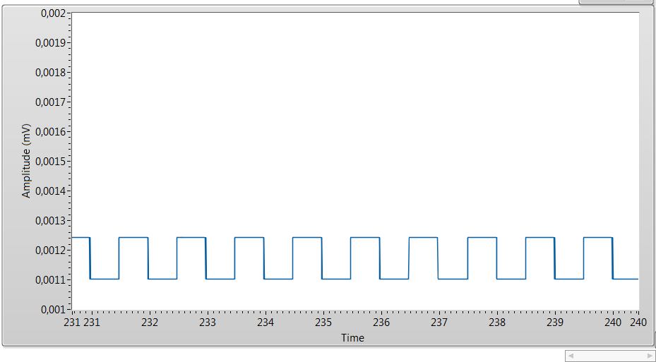
In my system though,I only get positive values:

ps: Ignore the amplitude value, they aren't in mV.

The thing is, even if my conversion was wrong (2's complement), wouldn't I supposed to have 0 and 1 as MSB when looking at the raw data (if it is 0, the value is positive, and 1 is negative) ?

This is the raw data from channel 1:

Those are the two values I get. Both positive right??

Am I missing something here??

Thanks

  • Hey JJ,

    There are a couple of problems with that test signal. Not only is the mean value pretty high above zero volts, but the magnitude of the waveform is only 200 mV. What are the contents of your CONFIG2 register?

    Brian Pisani
  • These are the contents of my registers (reading from them)

    I am using bipolar mode (+- 2.5V) and using internal reference. VREFP is generated internally and it probes 2.5V.

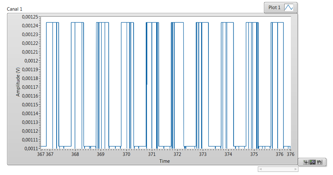
    I just found out an odd situation. The test signal is very "smooth" when I have 500 or 250 SPS.

    Although if I go to 1k (or higher) this is what happens:

    Any ideas?

  • Hey JJ,

    I definitely know what is going on with the crazy waveform. At the higher data rates your microcontroller is not collecting the data fast enough and the shift register gets loaded with the next sample before you finished reading the last. The result is that samples are corrupted and look like they are going all over the place.

    I have a theory about the magnitude and offset issue. I believe that you are converting the negative values to positive ones accidentally or before you think you are. The result is that when you plot the data it seems like its small and only positive. Instead of the signal going from 1.1 mV to -1.24 mV (or vice versa), its going from 1.24 to 1.1. One way to confirm would be to look at the data coming from the device on the oscilloscope and see if you identify any negative results.

    Brian Pisani
  • Hey Brian!

    Yeah, about the crazy waveform I thought that was the problem as well. Just needed a confirmation.

    And about the test signal, I think I get it now. I realized that my whole data set was being "shifted" in a wrong way.

    As you can see, channel[0] (STATUS) only starts at the end (C0) of the word and continues on channel[1] (ending with A which is my GPIO data that I set).

    It was a problem regarding they way C2000 (microcontroller I'm using) reads data from SPI registers.

    I set all channels to test signal and now they all seem to be going to both positive and negative.

    Thanks a lot for the help!