This thread has been locked.

If you have a related question, please click the "Ask a related question" button in the top right corner. The newly created question will be automatically linked to this question.

afe7225 EVM

Other Parts Discussed in Thread: AFE7225, CDCE72010

Hi,

I have a afe7225 EVM and TSW1406 and want to test the DAC performance. the CDC AUX input is 368.64MHz, output 0 divider is 3, output 2 divider is 8. divideDAC clock is 1, interpolation is 4. test file is :WCDMA_TM1_complexIF30MHz_Fdata122.88MHz-1000.TSW. I got the signal on the spectrum analyzer at 7MHz and the bandwidth is 2MHz, and there is a lot of suprious on the spectrum. what's wrong with my configuration or test file?

thank

David

  • Hi David,

    I believe the default interface is 2-wire DDR mode so change output 2 divider to 16.

    The input data rate for your current configuration is 30.72MHz. The WCDMA file you are using is 122.88MHz data rate so you cannot use this file.

    Thanks,

    Eben.

  • thanks. there is no 30.72MHz rate signal in the test file where can I get it?
    If I use the 122.88MHz data rate test file how can I change the configuration? change interpolation to 1 and output 2 divide to 4?
  • Download "software for creating high speed dac patterns" and use the commsignal pattern generator to create custom WCDMA patterns. Software is available here: 

    The users guide is available here: 

    If you want to test 122.88MHz input data rate:

    -Use GUI to change interpolation to 1x

    - Change output 2 divide to 4.

    Thanks,

    Eben.

  • Hi, Eben,

    thank you for the reply.

    when I change the output 2 divide to 4 the led D2 on the 1406 board is off . the test file can not load to 1406 board and there is nothing on the spectrum analyzer.

    thanks

    David

  • Hi David,

    TSW1406 is a low cost version of TSW1400 and may not support all input data rates of AFE7225. I will check and get back to you but consider using TSW1400 for high input data rates.

    Thanks,
    Eben.
  • Hi, Eben,
    any update?

    thanks
    David
  • Hi, David

    I designed the firmware of TSW1406 and it supports up to 500MHz to DAC interface. As TSW1406 is low cost version of pattern transmitter, there is a limit of pattern size which is 64K of I & Q samples due to internal DPRAM size. While TSW1400 has 1GB of external SDRAM onboard to load one frame size of LTE pattern, which helps to measure EVM (Error Vector Magnitude). Other than EVM measurement, general spectral measurement is ok with TSW1406.If you transmit full size of LTE pattern from HSDC Pro, the first 64K of I & Q samples shall be loaded into internal memory of FPGA and deliver this pattern to DAC. With this, you can measure spectrum without any problem.


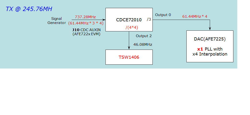
    For AFE7225EVM settings, below is default settings. I suggest to create tone from HSDC Pro and measure it from spectrum analyzer to see the correct tone location first. Below is the setting for 245.76MHz of data rate for TX. You can refer to this and modify clocking based on your operation.

    Thanks,

    KW

  • Thank you very much. KW.

  • Hi, KW,
    I set the CDC AUX in to 737.28MHz, CDCE72010 output0 divider 3, output 2 divider 16, test file with WCDMA_TM1_ComplexIF30MHz_Fdata245.76MHz-1000.tsw.
    when I set X1 interpolation I can have 30MHz center frequency signal on spectrum analyzer, but the bandwidth is only 1.2MHz
    when I set X4 interpolation the center frequency is change to 7.5MHz, signal bandwdth is still 1.2MHz.
    is there something wrong of it?

    thanks

    Pingsheng
  • Hi, David

    The clock diagram above is for x4 of interpolation case and sampling clock is 245.76MHz for DAC. In this case, the input data rate should be 61.44MHz (=245.76MHz/4). So the data rate from HSDC Pro should be 61.44M.
    For x1 interpolation, you should change clock scheme.
    For x4 interpolation with 245.76MHz of test pattern, I expect you'll get this result (7.5MHz (=30M/4) located with 1.25MHz (5MHz/4).

    Thanks,
    KW
  • Hi, KW,
    I don't have 61.44M test file. if I use 245.76M signal and X1 interpolation, how should I change the clock scheme?

    thanks

    Pingsheng
  • Hi, David

    You can download pattern generator from TI website (TSW1400EVM). The name of SW is "Software for creating High Speed DAC Pattern" and you can create 61.44MHz of sample rate. In general, 61.44MHz of input rate with x4 interpolation is more standardized architecture rather than 245.76MHz of input rate with x1 interpolation. You can set /4 from output 2 for x1 interpolation.

    www.ti.com/.../TSW1400EVM

    Thanks,
    KW
  • Hi, KW,

    You are right , the signal is 7.5MHz and 1.25 MHz bandwidth. when I change to x1 interpolation the signal is in 30MHz but the bandwidth is still 1.25MHz. the signal is not clear, there is a lot of spurious.

    thanks

    Pingsheng