This thread has been locked.

If you have a related question, please click the "Ask a related question" button in the top right corner. The newly created question will be automatically linked to this question.

ADS1292R Interfacing problem with STM32: Noisy Channel 2

Other Parts Discussed in Thread: ADS1292RECG-FE, ADS1292R, ADS1292

Hello all,

I am trying to interface ADS1292r with STM32L151rd ARM processor via SPI (32MHz system clock, 1MHz SPI clock). Following ADS1292RECG-FE, the design circuit stands:

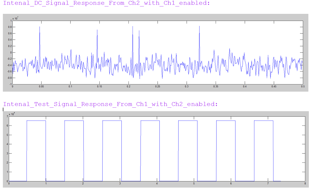
From channel 1, MCU can read internal 1Hz test signal well, also external signal (10mVpp) provided from signal generator.

But, for channel 2, clean output for internal 1Hz test signal only when channel 1 is disabled. Also, irregular/ noisy channel 2 when external signal (10mVpp) applied from signal generator.

LA, LL electrodes are also shorted following sample circuit provided in ADS1292 datasheet. Still noisy. What could be the reason for that ? Do I need to modify circuitry for channel 2 ?

With the following configuration, I'm finding noisy waveform across PGA2P and PGA2N pins via oscilloscope.

/*ECG_Reg_SendData(register_address,value)*/

ECG_Reg_SendData(0x01,0x03); //Set sampling rate to 1 KSPS, continuous conversation
ECG_Reg_SendData(0x02,0xA0); //Lead-off comp off, test signal disabled, 2.4V ref buffer on, 
ECG_Reg_SendData(0x03,0x10); //DC Lead-off defaults
ECG_Reg_SendData(0x04,0x30); // Ch 1 enabled, gain 3,connected to electrodes.//
ECG_Reg_SendData(0x05,0x30); // Ch 2 enabled, gain 3,connected to electrodes. //
ECG_Reg_SendData(0x06,0x00); //RLD settings: disable. 
ECG_Reg_SendData(0x07,0x00); //Default LOFF settings: all disabled

ECG_Reg_SendData(0x09,0xEA); //Respiration Channel ON, phase angle 112.5 for 32 KHz gain 3, 4 //
ECG_Reg_SendData(0x0A,0x03); //Respiration: Calib OFF, respiration freq 32 KHz, RLD-Ref internally //

I request your kind help in this regard.

Thank you,
M

  • Hi M,

    Welcome to the e2e forum!  I see you managed to post the same thing twice, so I'm going to delete the second instance.  Can you try shorting channel 2 at the chip, and then move out to your electrodes (short the inputs at R38/R39 on the chip side, and then on the electrode side...) and see if that makes any difference?  

  • Hello Tom,

    Thank you for your response. Yes, second post was for network issue, deleted.

    I'm working with a custom build PCB. Are you suggesting for input short test for channel 2 (001 to MUX2[3:0] and shorting LL and RA of my design?). I found a fixed output value for that around 65400.

    I request to know any other way to check. I tried to connect chest electrodes directly to RA, LL connectors and also found noises.

    This is my code for testing. Am I missing any configuration here.

    Thank you,

  • Hi again MHI,

    When there is 'noise' in the output data of an ADC, the easiest way to track down where it might be coming from is to short the inputs at various stages of the analog input signal chain to see where it might be coming from. So starting right at the chip, short the inputs and look at the data. If it's clean, move backwards down the signal chain untill you get to the end of the line - the electrodes in this case.
  • Hello again,

    I've checked external circuitry. I'm wondering what could be the reason for this behavior of Channel 2 : When channel 1 is enabled, internal 1Hz test signal and input short test do not work for Channel 2. Works only when Channel 1 is disabled (0x80 to 0x04 register). No such problem for Channel 1.

    Am I missing something in circuit? AVDD supply 2.8V and DVDD 1.8V from two regulators. Voltage Ref internal 2.4v. I've measured: VCAP1= 1.18v, VCAP2= 4.8V, VREFP = 2.4V. GPIO pins not connected. Have anyone noticed the same like me ?

    Another query: Is it the correct data interpretation (2.4V internal ref with gain 4):

    Scale_factor= (Vref/gain)/2^23-1= (2400mV/4)/8388607= 0.000071525 mV
    for a count 65531 = (65531*Scale Factor)=4.68714mV

    Thank you,

    M

  • Hi MHI,

    Have you tried this test with another board or another chip?  I can't think of any reason why the internal test signals should be corrupted on CH2 only if CH1 is enabled.  Screen shots of what you are seeing would be helpful.

  • Hello,

    With sample rate 1Kbps, respiration disabled and Test signal (0xA3 to 0x02 register and 0x05 to 0x04 for ch1 and 0x05 to 0x05 register for ch2), this is the result: X-axis (Sec), Y-axis (Count Values).

     Internal_DC_Signal_Response_From_Ch2_with_Ch1_disabled: count value 65451

    (Channel disabled by sending 0x80)

     To convert count values to voltage: is the scale factor: 0.000047683?

    (Scale_factor= (Vref/gain)/(2^23-1)= (2400/6)/8388607= 0.000047683 mV)

    Then this amplitude becomes 3.12 mv !! 

    Other responses:

    This is my acquisition code:

    if (ECG_Acq_Flag == 1)    // DRDY interrupt from EXTI pin                                                           

    {

     // read 1st 3 byte status register (1100 + LOFF_STAT[4:0] + GPIO[1:0] + 13 '0's) and discard                         

      /* 8-bit 1st Status data read and discard*/                                                        

                                while(!SPI_I2S_GetFlagStatus(SPI2, SPI_I2S_FLAG_TXE));  //transmit buffer empty?

                                SPI_I2S_SendData(SPI2, 0x00);       //Dummy byte to generate clock

                                while(!SPI_I2S_GetFlagStatus(SPI2, SPI_I2S_FLAG_RXNE)); //data received?

                                 SPI_I2S_ReceiveData(SPI2);                           

    /* 8-bit 2nd data read and discard*/                                                                     

                                while(!SPI_I2S_GetFlagStatus(SPI2, SPI_I2S_FLAG_TXE));  //transmit buffer empty?

                                SPI_I2S_SendData(SPI2, 0x00);       //Dummy byte to generate clock

                                while(!SPI_I2S_GetFlagStatus(SPI2, SPI_I2S_FLAG_RXNE)); //data received?

                                  SPI_I2S_ReceiveData(SPI2);            

    /* 8-bit 3rd data read and discard*/                        

                                while(!SPI_I2S_GetFlagStatus(SPI2, SPI_I2S_FLAG_TXE));  //transmit buffer empty?

                                SPI_I2S_SendData(SPI2, 0x00);       //Dummy byte to generate clock

                                while(!SPI_I2S_GetFlagStatus(SPI2, SPI_I2S_FLAG_RXNE)); //data received?

                                  SPI_I2S_ReceiveData(SPI2);

    /* 24-bit signed data Channel [0,1] read and store in 32-bit register */       

                                   for(i = 0; i < 2; i++)

       { 

          channelData[i] = 0;     

          // read 24 bits of channel data in 3 byte chunks

          for(j = 0; j < 3; j++)

          {                                /* 8-bit data read starts*/

                                 while(!SPI_I2S_GetFlagStatus(SPI2, SPI_I2S_FLAG_TXE));  //transmit buffer empty?

                                  SPI_I2S_SendData(SPI2, 0x00);     //Dummy byte to generate clock

                                  while(!SPI_I2S_GetFlagStatus(SPI2, SPI_I2S_FLAG_RXNE)); //data received?

                                  tmpE=SPI_I2S_ReceiveData(SPI2);

                                  /* 8-bit data read ends*/

             channelData[i] = ((channelData[i]) << 8) | tmp;

          }

         //      // convert 3 byte 2's complement to 4 byte 2's complement 

       if ((channelData[i] & 0x00800000) > 0) 

          {

             channelData[i] |= 0xFF000000;

          }

          else

          {

             channelData[i] &= 0x00FFFFFF;

          }                                                                                             

    // ECG_SD_write(filename);                                                

    printf("%d\r\n",channelData[1]); //  UART to log Channel 2 data                 

    ECG_Acq_Flag = 0;  // Reset ECG DRDY interrupt flag.                      

    }

    }

  • Hi,
    I have also checked another chip (another custom PCB). Same response.
    Do the ADC have any voltage limit (Max ?) It is 2.4 volt, right ?
    Also, my supply voltage 2.8V (AVDD) should be Ok here, I found some schematic using 3.3V AVDD.

    Thank you.
  • Hi MHI,

    2.8V AVdd should be fine, as should the 2.4V reference. I've tried re-creating your problem with our board and I'm not able to see any issues. Please do me a favor and read back your register settings to be sure you are programming the ADS1292 like you want it setup. Once you have that, please post back the results here.
  • Yes, I've checked those registers after writing values to them, they are OK. What I'm suspecting, any soldering issue in PCB. I'm buying a breakout board to see the difference. Once I test with breakout board, I'll post the result. 

    BTW, is my calculation right: Scale_factor= (Vref/gain)/2^23-1= (2400mV/4)/8388607= 0.000071525 mV

    For a count 65531 = (65531*Scale Factor)=4.68714mV ?

    And 2's complement conversion?

    Thank you for your kind time spending in this regard.

    MHI