This thread has been locked.

If you have a related question, please click the "Ask a related question" button in the top right corner. The newly created question will be automatically linked to this question.

AFE4300EVM-PDK Calibration

Other Parts Discussed in Thread: AFE4300EVM-PDK, AFE4300

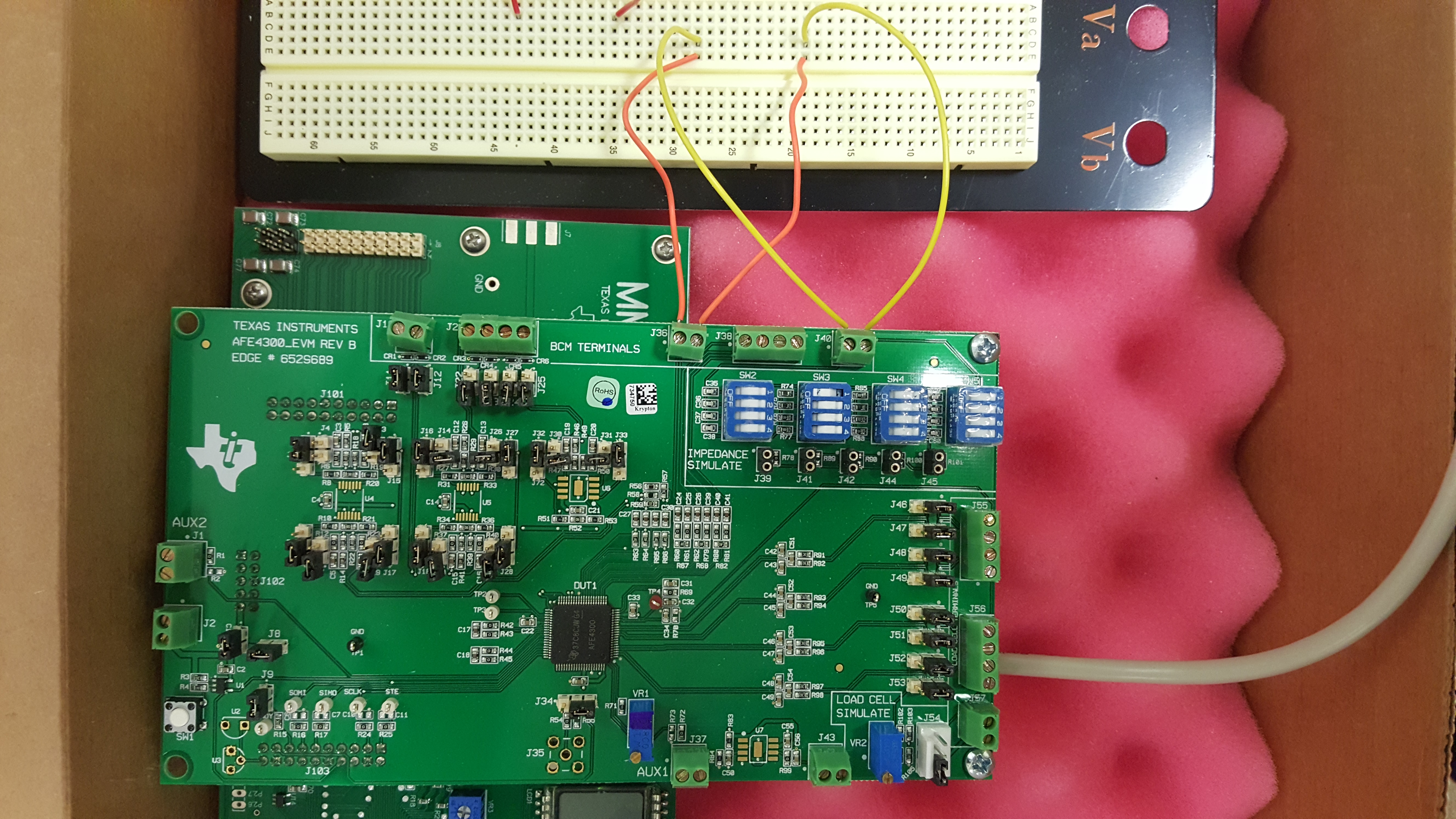
Hi, I am having trouble getting the correct results from a hand to hand measurement with the AFE4300EVM-PDK and wondering if you could help. I have followed the SBAU201A and SBAA202 pdfs and calibrated the unit, getting results inline with figure 9 of SBAA202. When I go and put the leads onto a body simulator I get results a reasonable amount lower than expected. I have tried this on more than one simulator and this seems consistent.

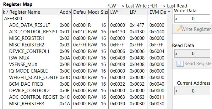
I'm stumped as to what is going on. I've measured across R56 and R57 and got 701ohms and 952ohm. I'll get the parts for the compex network in figure 11 to test against the provided results but perhaps this is an issue with the impedances between VSENSE to IOUT???

Hope I'm doing something obviously wrong and if you need more information I'm happy to provide.

Cheers,

Cameron

  • Hello Cameron,

    Are you using the BCM signal chain in FWR mode or IQ mode?
    Does the body simulator also emulate electrode impedance? If it does, what is the electrode impedance?
    What is the range of the impedance you are measuring using the body simulator?
    Can you provide the AFE register settings and the test results?
  • Hi Parveen,

    I'm using FWR and testing it with two body simulators I made awhile ago. They both have have electrode impedance of about 250 ohms at 50 khz. Not sure why I chose this so maybe this is wrong. The impedance between sides is about 550 ohms. I'll get another chance to look at this in a few days and get regerster  settings.  Apart from that I'll test it with the complex network provided in figure 11 of SBAA202

  • Another Issue, I've changed computers and now I'm getting error code 1003 on the software. I've tried all the usual things like uninstall and reboot and nothing has helped so far. Is this a common problem? I initially don't think I installed in admin mode but subsequent attempts were all as admin.

  • I've have put a screen shot of the register tab below. This time I've tested across a 560 ohm resistor with no input impedance and it is still low. Hope there is a clue to the register values.

  • Any chance of some help??
  • Hello Cameron,

    I do not see any issues with the register settings.
    Do you use the BCM measurement tab or configure the settings directly?
    Are using 4-wire or 2-wire measurement when you tested the resistor?
    If you are using 2-wire, are the shunts placed on J11 and J12?

    Additionally there is also an on-board impedance array block.
    To connect the on-board impedance array to the IOUT0-1 and VENSE0-1 channels, connect a wire between J36 - pin 1 to J40 - pin 1.
    Another wire between J36 - pin 2 to J40 - pin 2. In addition to that, place shunt jumpers on J11 and J12.
    I have provided a table below that lists the resistance I measured and the voltage measured using AFE4300.
    Could you measure the on-board impedance in your board and check if it matches with your board (you could use the same register settings)?

    SW Ohms Volts
    SW4-1 10.45 2.6E-3
    SW4-2 100.53 66.6E-3
    SW4-3 300.6 208.4E-3
    SW4-4 500.3 349.5E-3
    SW3-1 601.7 421.2E-3
    SW3-2 750.3 525.8E-3
    SW3-3 1000.8 701.5E-3
    SW3-4 1499.1 1.05
  • Hi Praveen,


    Thanks for the reply. I set it through the tabs and not directly. I had tried both four wire and two wire tests with J11 & J12 shunts placed for the two wire tests.


    Below are the results for the 8 SWx-x settings where "Measured Ohms" is measured with a multimeter.

    SW Ohms Volts Measured Ohms
    SW4-1 5.7 4.62 E-3 10.5
    SW4-2 8.9 6.25 E-3 100
    SW4-3 243 170 E-3 300
    SW4-4 366 255 E-3 500
    SW3-1 420 293 E-3 600
    SW3-2 490 342 E-3 750
    SW3-3 590 411 E-3 1000
    SW3-4 737 514 E-3 1500

    I also measured the resistance across R56-R59 (RP0,RP1,RN0,RN1) in case that helps

    R56 700 ohms
    R57 951 ohms
    R58 99 ohms
    R59 196 ohms

    I hope this reveals something, I notice now that SW4-1 voltage is the only one higher than your results, it's possible I recorded that incorrectly if that is unexpected. I've also attached a picture of the board just incase that will help as well


    Thanks again,

    Cameron

  • Hi Praveen,

    Sorry to be a nuisance but getting this working is looking to become a time critical job for us. It's been almost two months since I first flagged the issue, could you give me an idea of what your thoughts on the problem could be soon? I will have to look to return it as a faulty unit and try another one if nothing can be identified in the next week.

    Thanks,

    Cameron

  • Hello Cameron,

    I apologize for the delay in my response. Thanks for your patience and understanding.

    Based on your data for the 8 SWx-x settings, the ADC codes (volts) are different.

    In order to isolate if it is a data capture issue or faulty device, could you configure the registers directly instead of using BCM measurement tab and record the ADC codes for the 8 on-board resistor network (8 SWx-x settings)?

    Also I would like to know if you updated or modified the "Write Registers.csv" file located in the AFE4300 GUI installation directory (C:\Program Files (x86)\Texas Instruments\AFE4300 Device GUI)? This file is used for sequencing the commands for calibration and measurement of impedance in the BCM measurement tab.

    I have attached the file for your reference.

    /cfs-file/__key/communityserver-discussions-components-files/73/5327.Write-Registers.csv

  • Hi Praveen, still no luck. I used that "Write Registers.csv" file and set the registers via the "Low Level Configuration Tab", none needed changing but I again set each one anyway. I'm not quite sure what you mean by "ADC codes (volts)".

    Thanks,
    Cameron