This thread has been locked.

If you have a related question, please click the "Ask a related question" button in the top right corner. The newly created question will be automatically linked to this question.

AFE4404 CLK

Other Parts Discussed in Thread: AFE4404

Hello,

I have difficulty to understand the good using of the CLK of the AFE4404. On  the recommanded design we can seethis pin wired to MCU through a series resistor (500R) with a pulld owm (rshunt 500K).

- Is really necessary to connect this pin to the MCU when in internal clock mode ?

- Is necessary to use the 2 resistors in external or external mode ?

Best Regards,

  • Samuel,


    I've moved this post to the Medical Forum, where the AFE4404 is now supported. I'm sure you'll get an answer here.


    Joseph Wu
  • Samuel,

    Please refer to page 68 of the datasheet (typical application) for the answers to your questions.
  • Hello,

    I come back with another question about the CLK pin.

    - Iis it possible to connect a 4 Mhz (or more) oscillator to this pin ?

    - The CLK can be 4 to 60 MHz, is there an influence of using the lower of the higher frenquency ?

    Thanks,

    Sam

  • Sam,

    Yes a 4 MHz clock can be provided as an external clock to the device.
    The frequency range of the external clock can be between 4 MHz to 60 MHz.
    Depending on the external clock provided, you will need to set a division ratio such that the divided clock to the AFE is between 4 MHz to 6 MHz. Operating at the lower of the internal frequency range reduces the current consumption of the AFE (refer Figure 1 of the datasheet).
  • Hello,

    I come back on the same topic because I have another question about the AFE4404 Clock.

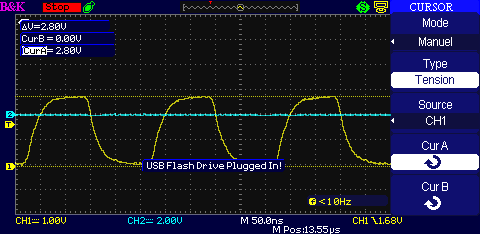
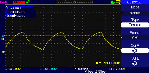
    Since 2 months I received my boards, a 4Mhz clock frequency  is supplied by a MCU and I placed a 499R resistor in series. I note distorsion of the CLK signal.

    Here is my signal took betwwen my MCU and the series resistor :

    Now the signal took after the resistor (between the series resistor and the CLK input of theAFE4404).

    We can see that the resistor creates a low pass filter.

    So my question is : is it possible to reduce the value of the series resistor to avoid this deformed signal ?

    I have to route again my PCB for different reasons so what kind of precaution can I take to minimize the capacitive effect ? (we can see on the first screenshot before the series resistor that rise and fall time are already important, certainly due to the parasitic effect).

    Sam,

  • Hi Sam,

    Based on the timing waveform on the CLK input of the AFE4404, the rise time is ~100 - 110 ns.
    With 500 Ohm series resistor, the total capacitance comes to ~200 - 220pF.
    The capacitance on the CLK pin from the AFE is < 4pF and typically the capacitance on a 50 ohm trace in FR4 is 3.3 pF/inch which implies the capacitive loading might be coming from the probe itself.

    Can you check your probe's bandwidth and capacitance?

    The series resistor was to prevent a case where an external clock is driving the input but at the same time, the device is operating in internal oscillator mode and trying to drive the clock pin (this could be possible before the device gets reset).
    In this case, the 500 Ohm limits the current between the two conflicting drivers.
    If it is too low, it will not provide effective current limiting.
    If it is too high, the R-C (where R=500 Ohm and C is the parasitic cap of the CLK line) will cause the clock waveform transient to go bad.

    As I mentioned before, C from the device is 4 pF or less. Assuming trace gives another 4 pF, a 500 Ohm resistor would give an R-C product (time constant) of 4 ns, which should be ok as long as the clock period is not too small.
  • Hi,

    Thanks for the help. Effectively it was the probe. I reduce the input capacitance of the probe in passing in x10 (this reduces the capacitance).

    Just to be sure, in your developement kit it's a 499R, 470R is too away or it's good ?

  • Hi,

    470R should be fine.