This thread has been locked.

If you have a related question, please click the "Ask a related question" button in the top right corner. The newly created question will be automatically linked to this question.

ADS1256 is burned out?

Other Parts Discussed in Thread: ADS1256

Hi all,

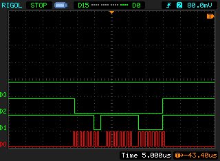
I supplied digital Vdd pin of ADS1256 with +5v dc accidentally. That was my first run. Now i am sending SYNC, WAKEUP and RDATA commands. Logic analyzer screenshot is attached.

D0: SCK

D1: MOSI

D2: MISO

D3: DRDY

I did not monitor chip select pin but it works fine. Do you think my chip is burned out ?

regards

  • Hi Altay,

    Welcome to the TI E2E Forums!

    The Absolute Maximum Ratings table in the ADS1256 datasheet specifies 3.6V as the maximum DVDD voltage. Above that limit, it is very possible to cause permanent damage, which could mean either degraded performance or loss of function.

    From the oscilloscope screenshot, I see that the MISO pin is toggling, which shows that there is some functionality.

    The MOSI appears to be sending 0x03 0xFF 0xFE, which would correspond to RDATAC, WAKEUP and RESET. During these commands the MISO pin will not send any data. Does reading data return valid results?

    Best Regards,
    Chris

  • Hi Christopher,

    I am interpreting my logic analyzer data as follows

    1st byte : 1111 1100 (0xFC) SYNC command

    2nd byte: 1111 1111 (0xFF) WAKEUP command

    3rd byte: 0000 0001 (0x01) RDATA command

    am i wrong?

    regards,

    Altay

  • Hi Altay,

    Sorry, I got the signals mixed up; you're right about the SPI commands. For the SYNC, WAKEUP, and RDATA commands...

    • Make sure the t11 delay time is included between the SYNC and WAKEUP commands.
    • Also the RDATA command should be issued after /DRDY goes low, and should be followed by three NOP commands  (0x00 - same as WAKEUP), to clock out the data.

    Best Regards,
    Chris

  • Hi Christopher,

    I have 7.68 MHz oscillator frequency. So i have 0.1302083 micro seconds master clock period. I calculate t6 delay as 6.51 micro seconds and t11 dealy as 0.52-3.12 microseconds for 4 and 24 tCLKN respectively. I put 10 micro seconds delays between commands. DRDY pin of my chip does not go low. I don't have any hope but can you check my loop for future works? Here is my code.I am using arduino due.

    #include <SPI.h>
    
    /* ADS1256 Registers (see p30) */
    #define   STATUS  0x00 //Status Control Register 0
    #define   MUX     0x01 //Multiplexer Control Register 0
    #define   ADCON   0x02 //A/D Control Register 0
    #define   DRATE   0x03 //A/D Data Rate Control Register 0
    #define   IO      0X04 //GPIO Control Register 0
    #define   OFC0    0x05 //Offset Calibration Coefficient Register 1
    #define   OFC1    0x06 //Offset Calibration Coefficient Register 2
    #define   OFC2    0x07 //Offset Calibration Coefficient Register 2
    #define   FSC0    0x08 //Full scale Callibration Coefficient Register 0
    #define   FSC1    0x09 //Full scale Callibration Coefficient Register 1
    #define   FSC2    0x0A //Full scale Callibration Coefficient REgister 2
    /* ADS1256 SPI Commands (see p34) */
    #define   WAKEUP    0x00  //Completes SYNC and exits standby mode
    #define   RDATA     0x01  //Read data
    #define   RDATAC    0x03  //Read data continously
    #define   SDATAC    0x0F  //Stop read data continously
    #define   RREG      0x10  //Read From Register rrrr
    #define   WREG      0x50  //Write To Register rrrr
    #define   SELFCAL   0xF0  //Offset and gain self-calibration
    #define   SELFOCAL  0xF1  //Offset self-calibration
    #define   SELFGCAL  0xF2  //Gain self-calibration
    #define   SYSOCAL   0xF3  //System Offset Calibration
    #define   SYSGCAL   0xF4  //System Gain Calibration
    #define   SYNC      0xFC  //Synchornize the A/D Conversion
    #define   STANDBY   0xFD  //Enter Sleep Mode
    #define   RESET     0xFE  //Reset To Power UP values
    
    const int CS = 10;  //Slave select pin
    
    void setup() {
      // start the UART library:
      Serial.begin(9600);
      // start the SPI library:
      SPI.begin();
      SPI.beginTransaction(SPISettings(1000000, MSBFIRST, SPI_MODE1));  //1MHz clock speed,most significant bit first, CLPOL=0,CPHA=1
      pinMode(CS, OUTPUT);
    }
    
    void loop() {
       digitalWrite(CS, LOW);  //CS active
       SPI.transfer(SDATAC);
       SPI.transfer(SYNC); 
       delayMicroseconds(10);
       SPI.transfer(WAKEUP);
       delayMicroseconds(10);
       SPI.transfer(RDATA);
       SPI.transfer(0x00);
       SPI.transfer(0x00);
       SPI.transfer(0x00);
       digitalWrite(CS, HIGH); //CS inactive
       delayMicroseconds(200);
    }
    

  • Hi Altay,

    The only thing that I would change is the delay time after the WAKEUP command. The ADS1256 will require 210 us between synchronizing and when data is ready (refer to table 13 on page 20 of the ADS1256 datasheet).

    Best Regards,
    Chris
  • Sorry i missed out settling time. Thanks for it.