This thread has been locked.

If you have a related question, please click the "Ask a related question" button in the top right corner. The newly created question will be automatically linked to this question.

ADS1120 DRDY not working

Other Parts Discussed in Thread: ADS1120, MSP430FR5969

Hi there,

I am using ADS1120 with internal clock, external reference (REFP0/REFN0) to convert an unipolar signal between AIN0 and AVSS, gain 1, bypass mode, continuous conversion, giving me the configuration values of: 0x81 0x04 0x40 0x00.

I can write those bytes and check the SPI signal on oscilloscope. Also, I can double check the write by reading the registers from ADS1120 with RREG.

After the start conversion command, though, no change occurs with the DRDY signal (always high) indicating no conversion was performed...

Extra information:

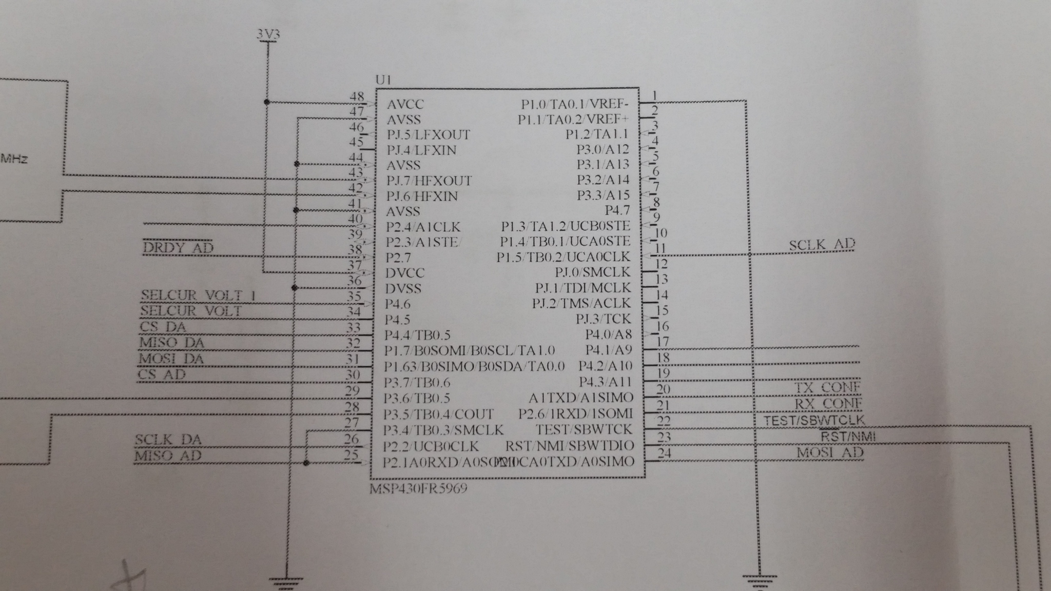
1-using a msp430fr5969 to interface with ads1120;

2-following the sequence from datasheet: reset adc, delay, write registers, etc;

3-tried single shot mode and same happens.

Any clue about it?

Thanks in advance,

Alex

  • Hi Alex,

    Welcome to the forum! Your ADS1120 should be working based on the information you have sent.  It would be helpful if I could see your schematic.  Can you send me a picture of the oscilloscope display showing the communication?  Also, what is your SCLK frequency?  One other thing is to make sure you are monitoring DRDY and not DOUT/DRDY.  Also DVDD is next to DRDY and depending on how you are probing you might be seeing DVDD.

    Thanks,

    Bob B

  • Hello Bob,

    First of all, thanks for the fast reply.

    I will provide you the schematic and oscilloscope display pictures, but in the meanwhile, I am answering your questions:
    1-I am using 100 KHz SCLK;
    2-I am sure I am monitoring pin 14 (DRDY);
    3-I am very careful about monitoring only DRDY pin with oscilloscope probe.

    Regards,
    Alex
  • Hi Alex,

    One other thing to do when you first apply power is to make sure the device is really active following power up. You can make sure that the ADS1120 is working by observing DRDY go low approximately 50ms after power is applied prior to writing anything to the device.  The startup behavior is to take one conversion and then power down.  Let me know if you see this response.

    Best regards,

    Bob B

  • Yes, Bob,

    I can see the DRDY going low right after the power-up. But after that it stays always high.

    Alex
  • Before setting any of the registers, can you send the START command to see if that is working at all?

    Bob B

  • Hi Bob,

    I tried to send the start command right at the begining, but nothing new happened. DRDY still goes low only after the power up.

    I'm attaching the pictures from SPI MOSI and MISO. Also the schematic. (soory about the extremely high resolution, by the way...)

    Thanks again,

    Alex

  • Hi Alex,

    Thanks for the info.  I may have not been clear about sending the START command.  Did you try sending the START command after DRDY goes low, or right after power up?  I was wanting to know if START was issued after the device returned to the power down state whether or not the device woke up and started a conversion.  I'm also curious if there could be an issue after the RESET command is sent, which is why I want to go back to the beginning and see if we can get something to work early on.

    I must say that this is very puzzling.  What is the AVDD supply voltage?  How is it derived?  Is there a connection between AGND and DGND?  If there is a voltage difference between the AVSS and DGND on the ADS1120 there may be an issue where the control signals are not getting properly passed between the analog and digital portions of the device.

    Do you have a voltage applied to the analog inputs to the ADS1120?  If so, you might try disconnecting the inputs to see if there is any issue related to the input voltage.

    Best regards,

    Bob B

  • Hello Bob,

    About the start command, I sent it after DRDY goes low. That makes more sense exactly because it returns to power down mode, as you mentioned.

    I also tried to send the start after a reset command and with no reset at all. Both gave me the same result.

    The AVDD is generated by a NCP551 chip with a 1uF cap to the ground as a filter.

    AGND and DGND are connected.

    There is no voltage difference between AVSS and DGND.

    About the input channel, I thought about it and left it open (no voltage at all).

    I agree with you...this is very puzzling! :)

    Regards,

    Alex

  • Hi Bob, good news!
    I transfered the ADS1120 to a simpler circuit and it works (basically with the same firmware). Thus, I assumed the problem was in my initial board. Looking carefully, I realized the DRDY was shorten with 3V3, not in the ADS1120 but near the MSP430 where the input pin for DRDY was right after the DVCC (you can see on the schematic I sent you before).
    Anyway, thank you very much for the suggestions and precious time.
    Best regards,
    Alex
  • Hi Alex,
    I'm glad you found the issue. Thanks for letting us know.
    Best regards,
    Bob B