This thread has been locked.

If you have a related question, please click the "Ask a related question" button in the top right corner. The newly created question will be automatically linked to this question.

ADC Selection with Single Ended Analog Input

Other Parts Discussed in Thread: ADS1220, ADS1262, ADS1255, ADS8681, TLV2333

Hi,

We are planning to use single channel ADC with the below specification due to the isolation requirement between channel to channel. We are planning to use 8

numbers of single channel ADC's to provide channel to channel isolation in more efficient manner. Could you please suggest us a best part number suited for the

design.

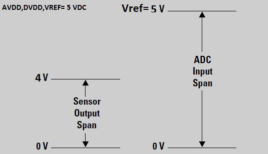
  1. Single ended analog input varies from 0V to 5V ( no differential input for us )
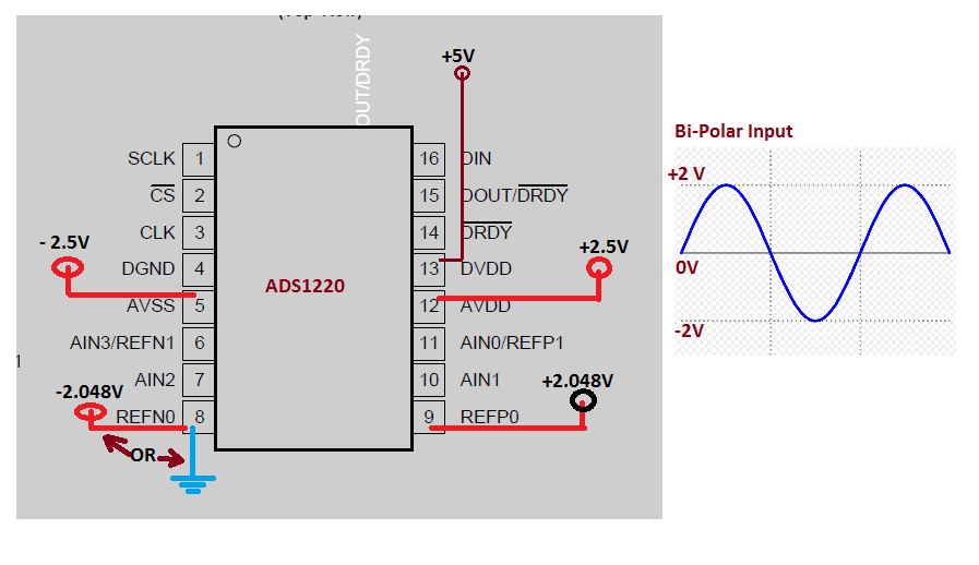
  2. Analog Power & Digital Power varies from 3.3V to 5V
  3. ADC Resolution is 20-bit or more
  4. Programmable input gain buffer ( gain from unity) on the ADC


Best Regards

Sharvy

  • Hi Sharvy,

    you may want to look at the ADS1220 in that case. However you will need an external 5V reference in order to measure 5V signals then. The analog supply also does need to be 5V if you want to measure 5V signals.
    A higher performance device would be ADS1255 or even ADS1262.

    Regards,

  • Hi.

    Thanks for the feedback.

    Our requirement is to use Single Channel Single Ended ADC for 8 different Analog input due to the tight isolation requirement. So please provide us a part number more align with this requirement?

    Best Regards

    Sharvy

  • Hi Sharvy,

    the suggested ADCs all meet your requirements. They can all measure one (and more) single-ended signal.
    We do not really have >20bit ADCs that only have 1 single ended input.

    Regards,
  • Hi,

    In the case of ADS1220, can I apply both AVDD and DVDD with + 5V supply

    Best Regards
    Sharvy
  • Hi Sharvy

    Have you considered the ADS8681 for this design? This device has integrated analog front end circuit that can support inputs signals up to +/-12V with a single 5V supply. It is a perfect device for single channel isolated module applications. 

    The only drawback is that the resolution for this device is 16-bits. What is the absolute resolution requirement for your design?

    Thanks

  • Dear Vinay,

    Thanks for the support guys!!.

    Currently, I don't have any negative input and the input ranges are from 0-5V with resolution 24-Bit with ENOB not lesser than 19 bit.

    Best Regards
    Sharvy
  • Hi Sharvy,

    you can use 5V AVDD and DVDD with ADS1220 as specified in the 'Recommended Operating Conditions' table in the datasheet.

    Regards,
  • Hi Joachim,

    I am re-opening this case. We are in the design stage. I need some more clarity on the ADS1220 device. Below are my doubts.

    From the datasheet of ADS1220 ( section 8.3.2.1 PGA Common-Mode Voltage Requirements ),  I can understand that, when the input PGA is enabled, the  PGA buffer requires some headroom. This means that the analog input must be at 200mV inside the power supply rails .

    1. Will it restrict the input range with in AVSS+200mV and AVDD-200mV?
    2. If so, how can I arrange the input voltage to the 0V to 5V exactly with out any offset or let me know any kind of biasing required for the 200mV offset.

    Best Regards

    Sharvy

  • Hi Sharvy,

    you are correct, when you enable the PGA and use a Gain=1, the inputs need to stay 200mV away from the supply rails.
    Means both the negative and positive inputs of the ADC need to stay within AVSS+200mV and AVDD-200mV. You cannot connect the negative input to AVSS in that case.

    In order to measure a single-ended signal that swings between 0V and 5V you HAVE to disable/bypass the PGA, use a AVDD >= 5V and an external 5V reference voltage.
    You could in theory also use the supply voltage as the reference source but I doubt you will get very good results with it unless your supply is really stable and has low noise.

    Regards,
  • Dear Joachim,

    Well said. So we will apply the AVDD and DVDD with +5.2 V to improve the noise margin. My initial requirement is to avoid the external Gain amplifier and

    provide required amplification to the low voltage input in the range of  0-100mV inside the ADC .

    1. If I need to apply the 0-5V input with PGA enabled with gain 1, Is there any method to avoid the buffer's 200mV offset? A wide guess, by applying a +200mV bias voltage on the AIN -ve pin is enough ?
    2. What will be the input impedance offered by the PGA under the condition enabled or disabled ?

    Best Regards

    Sharvy

  • Hi Sharvy,

    in case you want to use the internal PGA to amplify your 0V to 100mV signal you will have to level shift the input signal. Best case would be to level shift the signal to mid-supply.
    When disabling/bypassing the PGA you can still set the gains to 1, 2, and 4. You will not have to level shift the signal when the PGA is bypassed.

    You will not be able to measure a 0V to 5V signal when the PGA is enabled, even when you level shift the whole signal by 200mV and use a 5.2V supply. As you have to stay away from the supply rails by 200mV on each side you could at the most measure a 4.8V signal when level shifting by 200mV and using a 5.2V supply.
    Again, I recommend you disable/bypass the PGA in order to measure the 0V to 5V signal.

    In the ADS1220 datasheet we specify the input impedance in terms of absolute and differential input currents. You can see the typical input currents with the PGA enabled and disabled in the graphs in the datasheet on p.11ff.
    As you can see, the input currents (=input impedance) does not change much when disabling the PGA.

    In case you only need to measure one single-ended signal with the ADS1220, then I would recommend to use inputs AIN0 and AIN1 because they offer the lowest input currents.

    Regards,
  • Dear Joachim,

    Thanks for the detailed feedback.

    Our main requirement is to have the Input Impedance: Min 20 mega ohms up to 100 volts ranges & 230k Ohms up to 100 mv range

    As you know that, our input ranges are 0-100V , 0-4V , 0-100mV & 4-20mA-- Each input is applied to 4 different channels of the ADS1220 after the

    signal conditioning ( All the inputs are scaled to 0-5V using resistors )

    1) From the Absolute input current graph, I am wondering that the input impedance of the ADC is more than 1000 MOhm ( in the graph, the input current closer to 1-2 nA @input 2.5V and AVDD 3.3V). Am I right ??

    2) So can I remove the input Voltage follower buffer provided for the input impedance ?


    Best Regards

    Sharvy
  • Hi Sharvy,

    I did actually not know about your different input signal ranges. You didn't mention that before.

    If you only require 20MOhm of input impedance then you should be fine without the external voltage follower buffer even when you disable/bypass the internal PGA. You might want to keep the external buffer on your first prototype as a backup option.

    Why are you not dividing the voltages further down then, let's say to <=2V? That way you could use the internal voltage reference.
    Or will the resolution not be sufficient then anymore?

    Regards,

  • Dear Joachim,

    I am re-opening this thread again. We have started the design with ADC. I need some clarity on the below topic.

    Lets assume,

    • ADC will be having AVDD,DVDD & VREF with +5 VDC power .
    • If we have a sensor analog output voltage ( Input to ADC ) of 0-4V

    My Queries are given below,

    1. Can I apply this kind of variation in the input voltage span?
    2. Will there be any issue in the performance of ADC?
    3. Will that input captured properly by ADC ?
    4. What are the best method to provide give VREF voltage to ADC? Can I use Zener Diode for the Vref?

    Best Regards

    Sharvy

  • Hi Sharvy,

    yes, you can operate the ADS1220 with AVDD=DVDD=VREF=5V to measure a 0-4V input signal. The only important thing will be to bypass the PGA in that case (set bit PGA_BYPASS=1).
    This is a valid configuration of the ADS1220, therefore I do not expect any performance degradation and the 0-4V signal will be captured properly.
    As we are talking about a high resolution ADC, it would be recommended to use a precision voltage reference. For example a REF5050 or something similar.
    A Zener diode should work as well, but as the Zener voltage might have quite some variation you will probably see a large gain error.

    Regards,
  • Dear Joachim,

    Thanks for the feedback.

    Lets talk about the below scenario.

    If I am feeding VREF=AVDD=DVDD= 5V from the same power supply rail and restrict the Analog input voltage swing to 0-4V. There is a 1V margin ( 20%

    tolerance variation ) between the Analog input voltage span ( 0 to 4V) and the ADC input acceptance span ( Vref =5V ). 

    1. If there is a 20% tolerance variation in the Vref supply. It cannot alter our Analog input's capturing and performance of the ADC. What s your thought on  this? correct me if I am wrong.
    2. Can I avoid the VREF special IC and Zener diode from my circuit, if I am going for the above scenario? since we are looking for a low cost solution.

    Best Regards

    Sharvy

  • Hi Sharvy,


    as long as your input signal is smaller than the reference voltage you are using (assuming you use Gain=1 and bypass the PGA) you will be able to somehow capture the 0-4V input signal.
    However, please remember that the ADC outputs a code which is proportional to the ratio between VIN/VREF. Means if your VREF changes by 20%, you will have a 20% measurement error in your system. That is why it is extremely important to have a very stable and low noise reference source. I can therefore not recommend to use a supply with a 20% variation as the reference source.

    In the beginning you mentioned you are looking for 20bit resolution. If you target such high resolution numbers you will have to spend money for a proper voltage reference (or at least a good LDO that you can use as a reference). Your measurement will only be as good as your reference is.

    Regards,

  • Dear Joachim,

    Thanks for the feedback.

    For the Analog input range's 0-100V & 0-10V, We have decided to divide the input voltage to 0-4V ( to match the ADC reference swing )using precision resistors ( 1% 50PPM ). My question is:

    Will there be any issue or any kind of analog data missing if we choose to divide the Analog input voltage levels from the actual value to

    match our ADC input?


    Best Regards
    Sharvy
  • Hi Sharvy,

    thanks a lot for the update. Please keep in mind that the internal voltage reference of ADS1220 is only 2.048V. So in case you wanted to use the internal reference you have to divide the signals down even further. But you can certainly use an external 4.096V or 5V reference with the ADS1220 as well.

    Regarding your 2nd question, do you know what the smallest signal is that you want to resolve and what data rate you want to run the ADC at?
    For example when running the ADS1220 at 20SPS in Normal Mode using the internal 2.048V reference and bypassing the PGA, the ADC can resolve signals as small as 14uV (noise free). Converting this to the 100V range would mean you can resolve signals has small as ~700uV.

    Regards,

  • Dear Joachim,

    Thanks for the feedback.

    From your explanation I understand it as the follows: When we divide the signals down more, we will get more samples or data

    information or resolution rather than working at higher input voltages. Am I correct?

    Also I really want to know about the below parameters.

    1. We are not using any external oscillator sources. In the datasheet of the ADS1220, I couldn't able to find the internal oscillators

    frequency. What is the frequency of oscillation?

    2.How can I achieve all the sampling rates till 2ksps using the internal oscillator?

    Best Regards
    Sharvy
  • Hi Sharvy,

    I am not sure I really understand your comment: 'When we divide the signals down more, we will get more samples or data information or resolution rather than working at higher input voltages. Am I correct?
    You will have to divide the signal down to within the voltage range of the ADS1220 in order to measure it.
    If you want to save money and use the internal voltage reference, then your input signal to the ADC needs to be <=2.048V.
    You might get slightly better resolution when using an external 4.096V or 5V reference.
    If you could let me know what your requirements are in terms of resolution and accuracy you want to achieve for the 100V and 10V signal measurements I could probably give some more guidance.
    I believe as you intend to use 1% / 50ppm/°C resistors you should be fine with using the internal reference. Your system performance will probably be limited by the resistor divider then anyway.

    In principle you do not need to worry about the frequency of the internal oscillator. I didn't mention the frequency in the datasheet to avoid confusion.
    But here is how it works. In duty-cycle and normal mode, the internal oscillator runs at 1.024MHz. In Turbo Mode at 2.048MHz. To the user however it looks the same as using an external 4.096MHz clock in all modes. The ADC does have some internal clock divider that provides the appropriate clock to the core of the ADC.

    All the sampling rates mentioned in the datasheet can be achieved as stated with either the internal oscillator or an external 4.096MHz clock.
    If you are runnning from the internal oscillator, just set the data rate of the device to 2kSPS and select Turbo Mode. You will then get data at 2kSPS.

    Regards,

  • Dear Joachim,

    I will clear you more about the first question asked in the previous mail regarding the signal division.

    Imagine, if you can, that our 24-Bit ADC is capable of accepting voltages up to 100V. The input swings from 0 to 100V, which means that with each 5.96µV

    change in input voltage. Our ADC does not tolerate 100V, so we decided to heavily chop the input down to 0-5V. In this case, we are even getting better

    accuracy to smaller changes at the input, that is, with each 0.298µV change in input voltage.

    In the above case:

    Did we lose any resolution?

    Are we using it more effectively with the help of signal division ?

    Are we getting more sensitivity to the input ?

    More division will steal us some resolution?

    Best Regards

    Sharvy

  • Hi Sharvy,

    your calculations are very idealized and assume an ADC with a unipolar input voltage range. There is actually (almost) no 24-bit ADC on the market that truly achieves a resolution of 24-bits.
    But assuming an ideal 24-bit ADC with unipolar input voltage range, then you would be able to resolve the 100V signal with 100V/2^24=5.96uV and the 5V signal with 5V/2^24=298nV.
    As you are dividing the 100V signal down by a factor of 20, you need to multiply the 298nV by 20 again to get the resolution with respect to the 100V signal. So you see there is no resolution lost.

    If you look at the noise table of ADS1220 you will realize that the device does not offer 24-bit noise free resolution.

    Regards,
  • Dear Joachim,


    Thanks for the feedback.


    If we are applying a Bi-polar single ended input to the ADS1220 with an amplitude of +2V to -2V. From my engineers, there are two suggestions came across, which I have depicted in the below figure. One with REFN0 feeding with -2.048V reference ( negative reference) and other with REFN0 connected to Ground regardless REFP0 connected to +2.048V reference always. Please suggest us which schematic is correct to follow.


    Do we require an extra –ve reference voltage ( -2.048V connected to REFN0 ) to capture the full swing of the Bi-polar input?? If not!! how It is possible, since our input swing acceptance level is based on the VREF values provided in the corresponding VREF pins of ADC


    Or


    the AVSS ( -2.5V ) will be enough for the operation??


    Best Regards

    Sharvy

  • Hi Sharvy,

    This thread is moving more and more off the original topic.  I have just answered this question in the following post:

    https://e2e.ti.com/support/data_converters/precision_data_converters/f/73/p/519856/1889764#1889764

    Basically you would connect REFN0 to GND as the input range is +/-VREF for full-scale range.

    Best regards,

    Bob B

  • Dear Joachim,

    I am finding difficulty in getting the feedback on the below query already posted in Precision Amplifiers Forum . Please have a look in to the same. We would like to get the answer to proceed further.

    We are planning to use TLV2333 Op-Amp from TI, as the input buffer for the ADS1220 ADC device. The circuit will be operated in an industrial harsh environment. So we need to pass some tight standard to use the device in those filed. We are planning to feed the supply voltage of the Op-amp with +2.5V and -2.5Vrespectively on the V+ and V- pins. Our input ranges are between +/-5V and it will be divided down further by using a resistor network to get +2V and -2V to match the input swing of the Op-amp supply. We are planning to use a TVS diode to protect the circuit from 1kV surge pulse. Most of the TVS diode will provide a clamping voltage of 12-13V during the surge event and it last for a time period of 20micro second ( 8 micro second rise time ). As per the datasheet of TLV2333 it will with stand ESD pulses of around 4kV.

    My question is, whether it will ( TLV2333 ) survive the spike of 12-15V for 20uSec regardless of the maximum input value provided in the datasheet absolute maximum rating?

    Best Regards

    Sharvy
  • Hi Sharvy,

    in my opinion there is actually no real need to use an additional amplifier in front of ADS1220 for your measurement.

    The ESD ratings in the datasheet are not meant to protect from those surge pulses that you are describing. Just because the device mentions a 4kV HBM level does not mean it would survive a 1kV surge pulse.
    You have to implement a proper protection circuit externally to the device. TVS diodes are a definitely a good idea. On top you should add series resistors on the inputs to limit the input currents to safe levels below 10mA. Additionally Schottky diodes to the supplies might be useful as well.

    As long as you can guarantee that the TVS diodes will not pass more than 13V to the inputs of the IC, then limiting the input currents to <10mA using a series resistor (e.g. >2kOhm) will be sufficient to protect the OpAmp or ADC inputs.

    Regards,