This thread has been locked.

If you have a related question, please click the "Ask a related question" button in the top right corner. The newly created question will be automatically linked to this question.

ADS1220 signal is alwys high on Data Ready Pin (DRDY)

Other Parts Discussed in Thread: ADS1220, ADS1232, ADS1232REF, ADS1262, ADS124S06Hello, I am working on ADS1220 analog to digital board from olimex Board . Here is the link www.olimex.com/.../open-source-hardware an open source hardware for ads1220. I am working with STM controller for strain Guage application. I would like to tell you about my connection to loadcell , ADS1220 and STM board. SPI communication protocol running at 4.0 Mhz . Connections to Load cell are this way This is my connecton from loadcell to ADS1220 and from ADS1220 to STM Board. Here is my question. 1. Regarding my connections mentioned above i would like to use external voltage refernce Vref from Excitation volatge of Load cell. The load cell exitation volatge is nearly 5v is it ok? 2. Now i am facing a problem regarding DRDY bit status Its always high and never see the falling edge on it why? 3. I set the bit of power down register it worked fine but after that i am unable to see an interrupt on the pin DRDY. Is there a possibility that chip is gone to power down mode and never come back to active state if once set ? 4. If i connect the load cell exitation volatge as Vref to ADS1220 EX+(5v) and EX- then i observe that chip consumes most of the current and getting heated up ? 5. If its getting heated up means is the chip working or damaged? here are my register settings : Reg0 : 0x0E Reg1 : 0x04 Reg3 : 0x40
  • Hi Sandeep,

    When both the AVDD and DVDD are applied to the ADS1220, the ADC will take one conversion then power down.  If you want to take another conversion you must send the START command.  You can change the register settings to operate in continuous conversion mode and then issue the START command to start the conversions.

    It is hard for me to decipher your connections based on the information you gave me.  There is a bridge application circuit shown on page 56 of the ADS1220 datasheet in section 9.2.3.  This diagram demonstrates one possibility for how the connections could be made.

    It is also unclear as to how you are sourcing the AVDD and DVDD supplies.  If voltages are generated from two separate sources there could be a large potential difference between them, and so the grounds should be connected together with respect to AVSS of the ADS1220 and DGND of the ADS1220.  This may be a reason why your device is getting hot. 

    If AVDD is 5V, then you can use the 5V also for excitation.  You must also make sure that the excitation ground and AVSS are at the same potential (connected together). If you have exceeded one of the absolute maximum ratings, it is possible that you have damaged the ADS1220.  Your device should not get hot.  If it does, then you have an improper connection somewhere.

    As to the registers settings, they may or may not be correct.  It shows by register settings that you are connecting the reference to the REF0 input pair.  REFN0 must be connected to AVSS if that is the way you have your device connected.

    A complete schematic would be helpful instead of a description.  You can take the Olimex schematic and draw your connections on it.  Then send me a picture of your drawing if that makes it easier.

    Best regards,

    Bob B

  • Hello Bob, Thank for the quick response and your explanation. I am unable to send Images here . I had prepared the block diagram for my connections and sent to the mail id pa_deltasigma_apps@ti.com. But there was no response. Could you please check out Subject would me as ADS1220 Interfacing with STM32 Microcntroller. I attached the image file which gives you best understanding for you question. Thank you
  • Hello Bob,
    As my stm board has 5v and 3.3 volts supply so i connected AVdd with 5volts supply from board and Dvdd from 3.3v from same stm board and Avss and Dgnd are taken from the STM board ground so there is no issue of different potentials. As per your suggestion i will try to do rework and make according to your suggestions. Thank you.
  • Hi Sandeep,

    I found the email.  Just FYI, we don't monitor the email as closely as E2E, so it is always best to start your questions on the forum first.  If it becomes necessary we can email.  You should be able to attach files and pictures if you use rich format mode in the forum.

    In your block diagram you show REFP connected to GND and REFN connected to +5V excitation.  This connection would be backwards and incorrect. Also you show question marks for AVDD and AVSS and had a question on how to connect them.  If you applied a voltage to the reference input and have no voltage to AVDD this will case an issue and most likely damage the ADS1220.  If AVDD is less than the applied reference voltage you will most likely damage the device.  In your design AVDD should be connected to +5V and AVSS to GND.  I think we already covered that question previously.

    Unless both AVDD and DVDD are applied you cannot communicate to the ADS1220, nor will it make a conversion.  Both supplies must be fully applied for the part to work.

    When communicating to the ADS1220, CS must stay low throughout the entire communication transaction before returning high.  CS should not toggle with each byte unless it is a single byte communication (like issuing the START command).

    In the process of troubleshooting, I would not connect the load cell until you have the communication and the ADS1220 converting.  I would verify that the communication is working by writing to the registers and then reading back the contents to make sure the data is written correctly.  You may also want to look at the communication with a scope/logic analyzer to verify the timing and proper SPI mode format.

    Next check to make sure you can operate the ADS1220 in continuous conversion mode by correctly setting the register bit for continuous conversion and then sending the START command.  You should then be able to monitor the DRDY signal line and see it toggle at the specified data rate.

    Once you have verified communication you can move to the connection of the load cell.

    Best regards,

    Bob B

  • Hello Bob, I worked out the way you suggested and ADS1220 is working fine. Now the problem i have is invalid data when reading and writing in to register. When i write 0x80 in to the first register 0 and when I read the register it seems to be some thing other value as 0XCE. I am unable to find peoper way in finding the solution to this problem. Iam thinking that as the pins of MISO and MOSI are floting inputs and outputs is it the reason why i am getting this problem. I would like to set Pull up register son that they high. I here by attach my simple code to send and receive data from ADS1220. void ADS1220Config(void) { //ADS1220ReadRegister(ADS1220_0_REGISTER, 0x01, &Temp); // clear prev value; // Temp &= 0x0f; Temp1 |= ADS1220_MUX_0_G; // write the register value containing the new value back to the ADS ADS1220WriteRegister(ADS1220_0_REGISTER, 0x01, &Temp1); //ADS1220ReadRegister(ADS1220_1_REGISTER, 0x01, &Temp); // clear prev DataRate code; //Temp &= 0x0f; Temp2 |= (ADS1220_DR_20 + ADS1220_CC); // Set default start mode to 600sps and continuous conversions // write the register value containing the new value back to the ADS ADS1220WriteRegister(ADS1220_1_REGISTER, 0x01, &Temp2); } my spi Transmit and receive functions are this way void ADS1220SendByte(uint8_t Byte) { if(HAL_SPI_Transmit_IT(&hspi1,(uint8_t *)&Byte, sizeof(Byte))!= HAL_OK) { /* Transfer error in transmission process */ set_ERROR(); } } unsigned char ADS1220ReceiveByte(void) { uint8_t Result; if(HAL_SPI_Receive_IT(&hspi1,&Result, sizeof(Result))!= HAL_OK) { set_ERROR(); } return Result; } My seetings for SPI are : void MX_SPI1_Init(void) { hspi1.Instance = SPI1; hspi1.Init.Mode = SPI_MODE_MASTER; hspi1.Init.Direction = SPI_DIRECTION_2LINES; hspi1.Init.DataSize = SPI_DATASIZE_8BIT; hspi1.Init.CLKPolarity = SPI_POLARITY_LOW; hspi1.Init.CLKPhase = SPI_PHASE_1EDGE; hspi1.Init.NSS = SPI_NSS_SOFT; hspi1.Init.BaudRatePrescaler = SPI_BAUDRATEPRESCALER_2; hspi1.Init.FirstBit = SPI_FIRSTBIT_MSB; hspi1.Init.TIMode = SPI_TIMODE_DISABLE; hspi1.Init.CRCCalculation = SPI_CRCCALCULATION_DISABLE; hspi1.Init.CRCPolynomial = 7; HAL_SPI_Init(&hspi1); }
  • Hi Sandeep,

    Your code came back as one long single line and it is very difficult to follow code anyway unless I know the processor and compiler well.  Here is what you need to do.  Make sure that CS is or stays low throughout your entire communication.  Second, make sure that you are reading and writing on the correct SCLK edge.  It looks like it is ok from your code as far as I can tell, but the only good way to determine if your code is working correctly is by viewing the communication on a scope or with a logic analyzer.  If you have four channels available, look at CS, SCLK, MISO and MOSI.  Make sure that in each case the data is transmitted correctly and that it is also being received correctly.

    Send me any shots that you can capture if you can't solve the communication problem.

    Best regards,

    Bob B

  • Hello Bob, As you had suggested to keep CS pin always low I had done it and started communication with the chip. But i got to observe that during transmit of data from Microcontroller to ADS1220 has no error but while receiving after some time i get an error in function of SPI that means SPI communication error . I am sorry for not providing sufficent data regarding my controller. The controller i am connecting ADS1220 is STM32L053R8 and compiler used is Keil V5. I would send an email with some data and my code attachmnet with Scope images. Kindly go through it. Thanks
  • Hello Boob,

    I had sent a mail to pa_deltasigma_apps@ti.com with subject as : ADS1220 Interfacing with STM32 Microcntroller Unable to read data nor write the data kindly go through the mail Thanks

    Best regards,
    Sandeep
  • Hello Bob, Finally i am able to get the output volatge . I worked with mbed it works fine but with libabries given by ST doesnt work any ways thanks for the help and your time . if there any question regarding ADS1220 i would come back to you.
  • Hello Bob,

    I am able to get values from ADS1220 and I have few questions regarding calculation from voltage to weight.

    1Q. I got hex code from ADS1220 and converted it in to Volts The formula that i have used is  Vout = ((Hex_code _Ads1220/((1<<23)-1)) * (Vref/gain)) now my question is the hex code obtained is calculated with setting that we write in to register or without (Example : Reg0 is set with gain as 128)?

    2Q. could you give an application note on how to calculate weight from the hex code generated by ADS1220 as per data sheet i am unable to follow?

    3Q. I would like to do Tare Calculation is there any special command like 5 to 6 extra clock cycles for calibrating TARE weight as mentioned in ADS1232?  If available how do i do tare calculation.

  • Hi Sandeep,

    You can calculate the weight with a lot of math conversions from codes to volts to weight, but this will contain gain and offset error of the load cell and the ADS1220.  The easiest method is to use a two point calibration.  First point is no load, or 0 weight, on the load cell.  The result code is then referenced as 0.  Then place a calibrated weight near or at full capacity of the load cell.  This code then relates to the weight applied. 

    Let's say the capacity if the load cell is 1kg, and a 1kg weight was used for calibration.  The difference in codes from 1kg to 0 represents the measurement range of the load cell.  If you take the total number of available codes and divide that value into 1kg, you will get the weight value for 1 code.  When you Tare, you just adjust the 0 point of the measurement, but the scaling remains the same as per calibration.

    More detailed information regarding the calibration and calculation of weight (including the use of Tare) are detailed in the ADS1232REF user's guide.  The ADS1232REF is a weigh scale reference design.

    Best regards,

    Bob B

  • Hello bob, I am able to calculate values from ADS1220. But i could find drift for the change in weight. My load cell is 5Kg maximum with excitation voltage as 5v. Sensitivity as 18 to 20mv/v. When i start placing weight from 1 gram till 50 grams it works fine with exact weight calculation and from the 50 grams the additional of 1gram starts. According to my calculation  1Kg weight placed the reading is calculated to be 1023 grams  2 Kg weight placed the reading is calculated to be 2046 grams  For every weight increase there is a change of 0.023 grams/Kg. Can you please suggest me the best ways i can eliminate this problem.
  • Hi Sandeep,

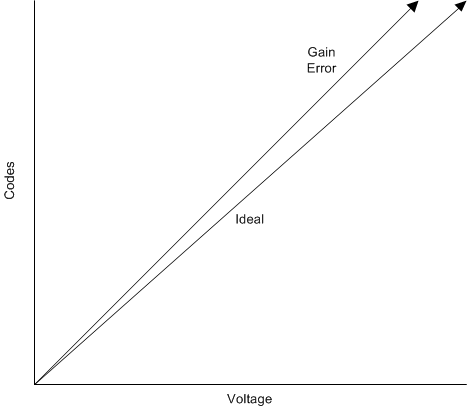
    What you are seeing applies more to gain error than to drift.  Drift is related to the changing of codes for the same weight value over time.  Gain error will appear small close to zero and increases in difference as a larger differential voltage is applied to the input.  Based on the information given the error is linear and can be calibrated out of the measurement.  Gain error is inherent to the PGA/ADC combination and will be different from device to device. 

    In my previous post I described a 2 point calibration.  To see the gain error and adjust for it you cannot use a small weight as the deflection is not large enough to be easily measured.  You need to use a calibrated weight at or near full-scale of the load cell capacity.

    In the picture example I show above you can see what gain error looks like and the differences in slope (the gain error in this example is above the ideal, but could also be below the ideal).  You need to establish a correction factor to adjust the gain error so that the measurement follows the ideal slope conditions.  The details on how to adjust are given in the ADS1232REF user's guide that I mentioned in the previous post.

    If you merely try to calculate the weight based only on the general characteristics of the load cell and the presumed excitation voltage (theoretical output of the regulator being used) then you will not account for the actual conditions nor the ADS1220 offset and gain error.  ADC offset error can be found by shorting the inputs, but this will not account for system offset.  Gain error as per datasheet Electrical Characteristics on page 6 shows the gain error can vary by as much as +/- 0.1%.  So to get any degree of accuracy you must calibrate or accept the measurement error. 

    According to the values you have calculated you would need to adjust by approximately 97.75% of the measured values.  Ideal/actual = 2000/2046 = 0.977517107

    1023 * 0.977517107 = 1000  which shows the values measured must be adjusted to correct for gain error to follow the ideal slope.

    Best regards,

    Bob B

  • Hello Bob,

    I had sent you an email regarding my question with images and few more details. Kindly go through the mail. My problem is i get 1 gram weight difference and rest of the bits are so noise and toggle. I had given an email to pa_deltasigma_apps@ti.com regarding it in details. Kindly suggest me the best soultion so that i can reallay remove noise. Thanks
  • Hi Sandeep,

    I doubt that you can achieve the type of performance you are looking for due to your configuration.  Basically you have a lot of wires acting as antenna for EMI/RFI pickup.  Your load cell cable has a shield wire, but has no positive affect as it doesn't connect to anything.  The ADS1220 has no input filtering for high frequency noise, which can alias back into the passband.

    The best approach is to develop a single board solution with good ground planes, analog filtering and correct shielding as opposed to the multi proto board approach and fly wires interconnecting boards.

    Best regards,

    Bob B

  • Hello Bob, As per your suggestion I had designed the input filter and EMI rejection filters in the schematics to reduce noise can you please go through the ADS1220 Schematics and would like to know is the input filtering for the board is enough or could you suggest me few more changes to reduce the noise. I had sent an attachment regarding to the mail id. Thank you.
  • Hi Sandeep,

    Unfortunately your email did not come through.  Can you try sending it again?

    Thanks,

    Bob B

  • Hello Bob,

    I had resent the mail. Please go through the mail. Thank you.
  • Hi Sandeep,

    I don't see anything schematically that will be a problem, but that doesn't mean you will solve all potential problems with this circuit.  It is not clear where the excitation voltage is being generated. There are a couple of approaches when making a voltage measurement.  One is by creating a very stable reference voltage with low noise and drift and using this same voltage as the excitation for the bridge.  This assumes that if the excitation/reference voltage is stable, then the bridge output should also be stable.  This becomes somewhat ratiometric with respect to drift, but not necessarily for noise.  Another approach is to precisely match the input filtering for both reference and analog inputs so that the noise appears more similar at the inputs so both drift and noise are cancelled ratiometrically.

    Load cell outputs are generally very small voltages requiring some gain.  When gain is introduced, the noise is gained as well as the signal.  Adding any additional filtering either at the reference inputs or the analog inputs may cause a disturbance in the ratiometric measurement, such as a phase change of the excitation noise relative to the analog input noise.  This very small difference (nV) when gained may appear as fluctuating codes.

    The worst sources for external noise is power-line cycle noise and EMI/RFI.  In your circuit you have lots of reference filtering, but the analog input filters may not match the same degree of filtering as the reference.  Currently you have zero ohm input resistance and are relying solely on the resistance of the load cell leads and bridge elements for the analog filtering.  This may be sufficient if the load cell cable is properly shielded and terminated.  Most likely you will need to experiment to see if you have sufficient filtering and shielding.  PCB layout is equally as important as the schematic components used.

    Best regards,

    Bob B 

  • Hello Bob,

    Thanks for suggestions and quick response you had provided me regarding ADS1220. This sensor works perfect for my application. Now I am trying for multiple load cell interfacing with the sensor.

    IN0 --> LoadCell1 Exc+  

    IN1--> LoadCell1 Exc-

    IN2--> LoadCell2 Exc+

    IN3--> LoadCell2 Exc-

    REF +- 5v

    REF--GND

    I had changed the register to Similar fashion as  ADS1220_MUX_0_1 | ADS1220_MUX_2_3 but i am able to receive the data from the load cell which is connected to mux 2 and 3 that means able to get weight calculation only from the load cell cell 2. My question is that is it possible to connect 2 load cells for the input channel. As I got this idea when I saw the data sheet as 4 channel. Was that true what I had assumed. In case if I can do so how to I read the individual load cell values and calculating the actual weight. Is there any application notes which states the interface of 2 or more load cell which would give me an idea to setup. Thank you.

  • Hi Sandeep,

    You can measure 2 different load cells, but not at the same time.  There is only 1 ADC in the ADS1220 with an input mux.  You select the input channels to be measured, but only one input pair combination can be converted at a time.  So you would take one load cell measurement, switch input channels and take the second load cell measurement.

    Best regards,

    Bob B

  • Hello Bob

    Thanks for your reply. I am little bit confused in selection of sensor for my load cell with respect to the precession. let me provide you my calculation regarding the sensor

    First Test with ADS1220:

    Gain : 128

    Ref Voltage = Avdd :5.03v

    Vdd = 3.3v

    Sampling rate : 20 SPS

    Sensitivity of load cell : 0.971 mv/v

    Full load Capacity : 300 Grams (Max)

    Full Scale Reading : Ref Voltage * Sensitivity of load cell = 4.88413 mV

    ADS1220 Peak to Peak Noise : 410 nV (As per the data sheet for gain and sampling rate setting )

    Resolution in grams : 0.025183605 g (until 0.0 is constant and then after the noise would affect the resolution which seems to be fluctuating.) + or - 0.02

    First Test with ADS1232:

    Gain : 128

    Ref Voltage = Avdd : 5.03v

    Vdd : 3.3v,

    Sampling rate : 20 SPS,

    Sensitivity of load cell : 0.971 mv/v

    Full load Capacity : 300 Grams (Max)

    Full Scale Reading : Ref Voltage * Sensitivity of load cell = 4.88413 mV

    ADS1232 Peak to Peak Noise : 110 nV (As per the data sheet for gain and sampling rate setting )

    Resolution in grams : 0.006797116 g (until 0.00 is constant and then after the noise would affect the resolution which seems to be fluctuating.) + or - 0.006

    Let's assume that I would like to measure the 150k weight.

    First Test with ADS1220:

    Gain : 128,

    Ref Voltage = Avdd :5.03v

    Vdd = 3.3v,

    Sampling rate : 20 SPS

    Sensitivity of load cell : 2 mv/v

    Full load Capacity : 150 KG(Max)

    Full Scale Reading : Ref Voltage * Sensitivity of load cell = 10 mV,

    ADS1220 Peak to Peak Noise : 4.10 uV (As per the data sheet for gain and sampling rate setting )

    Resolution in grams : 59.79125 g

    My questions regarding the sensor :

    1. From the above calculation I would like to select the chip in such a way that these are the requirements

    Accuracy : + or -0.1% Full scale.

    Resolution : 0.01N (Measuring range 50 Newton or ~5 Kg)

    Sampling rate : more than 1000 samples per second

    which would be the best suited chip for Texas instruments.

    2. I had tried working on the ADS1220 chip and found that for example if I place 200 grams weights and measured it to be as 199.987, 199.983,199.990,199.976. why is there fluctuations after one decimal point But i provided everything to be stable Vdd = 3.3 v (stable), AVdd = 5.0 v (stable), Gain = 128, Vref : 5.0 v is there a reason for this fluctuations

    3. internal reference voltage or external reference voltage which is the best to give as reference voltage which one is considered as best stable voltage.

    I am working on things to achieve best accuracy and resolutions and accuracy. Could you please provide me the best solution for the question. thank you.

  • Hi Sandeep,

    Your last set of calculations is using data rate of 1000sps, but you are showing 20ps.  It would appear that your target would be met for the 150kg load cell.

    For question 1, the accuracy of 0.1% of 50N is 0.005N and you desire a resolution of 0.01N.  To determine this you really need to know the full-scale range or sensitivity of the sensor used.  If this is a bridge type sensor, then the sensitivity of the sensor output is key to getting higher resolution.  To meet the 1ksps minimum you could possibly use the ADS1220, but you may need to use a lower noise ADC such as the ADS124S06 or the ADS1262.

    Regarding question 2, you kind of answered this yourself in the earlier calculations.  Due to conversion noise alone (not accounting for any external noise) you at best have a 0.025g resolution. The spread of the numbers given were from 199.90 to 199.76 which is 0.014g difference or within 1 noise-free count.  You also need to account for air currents (both across the load cell and ADC drift), vibrations and external noise from EMI/RFI as this will also affect your reading.

    For 3, you want the measurement to be ratiometric where the reference source is the same as the excitation source.  Any noise or drift in the excitation/reference will cancel in the measurement if it is ratiometric.  If different sources are used, then reference and excitation noise/drift will affect the outcome.

    Best regards,

    Bob B