This thread has been locked.

If you have a related question, please click the "Ask a related question" button in the top right corner. The newly created question will be automatically linked to this question.

Lead V in ADS1296 not working

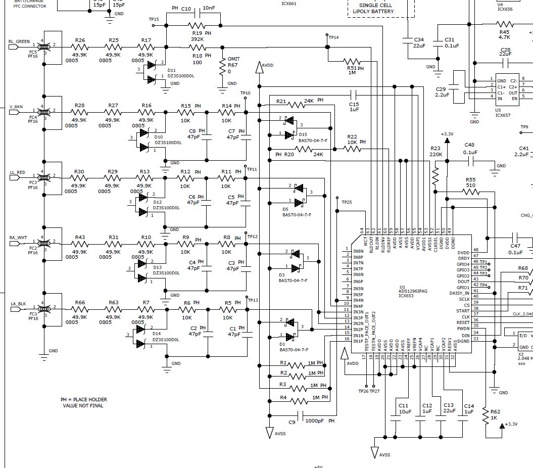
I have Lead V wired into CH4.  V is routed to IN4P and WCT is routed to IN4N so that V - WCT = Lead V.  Lead I(IN2P-IN2N), Lead II (IN3P - IN2N).  What does my CH4SET register need to be configured as if I want a gain of 2, 0x20?  If so what do my other CHnSET registers need to be configured as since Lead V uses the average from LL, LA, and RA I am assuming these should also be configured to 0x20?


  • Hey Eduardo,

    Your configuration of the CHnSET registers is correct. The key will be correctly setting the WCT1 and WCT2 registers since those control the multiplexer which switches the inputs to the WCT output. An example configuration that should work with your schematic would be WCT1 = 0x0A, WCT2 = 0xE3. Does this make sense?

    Brian
  • Brian - thanks for your time to answer my question.

    Ok, the WCT1 and WCT2 registers need to be set correctly for Lead V to work.  My config is WCT1 = 0x0B, WCT2 = 0xD4.  The example configuration you proposed, I believe will not work.

    For the WCT1 register, in my schematic, RA is connected to both IN2N and IN3N, I want WCTA powered on, so only 0x0B (using IN2N as RA) or 0x0D (IN3N as RA) should work. Am I misinterpreting something?

    For the WCT2 register, in my schematic, LA is connected to IN2P and LL is connected to IN3P, and I want both WCTB and WCTC powered on, it should be 0xD4.

    I tried both settings and none worked.  i still see some weird waveform that seems to be clipping when I switch to LEAD V.  Leads I and II and working perfectly

  • Hey Eduardo,

    I believe both should work since the order of which electrode goes to which amplifier since they are all identical. My advice would be to probe the WCT pin to see if the output there looks normal.

    Brian