This thread has been locked.

If you have a related question, please click the "Ask a related question" button in the top right corner. The newly created question will be automatically linked to this question.

HSDC Timeout ADC32RF45

Other Parts Discussed in Thread: ADC32RF45

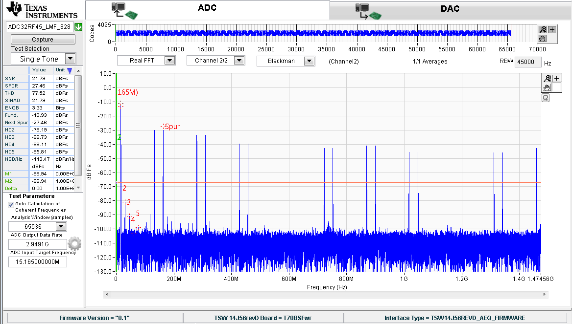
I have the ADC32RF45 evaluation board and the rev. D capture board. I have been successfully been able to get a FFT plot at a 2GHz sampling rate.

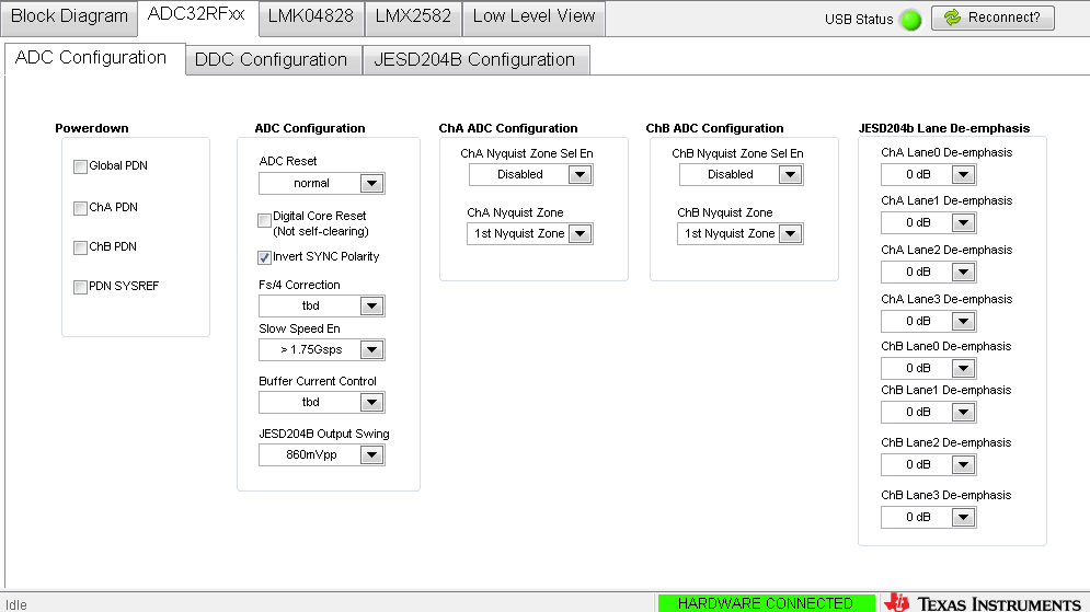
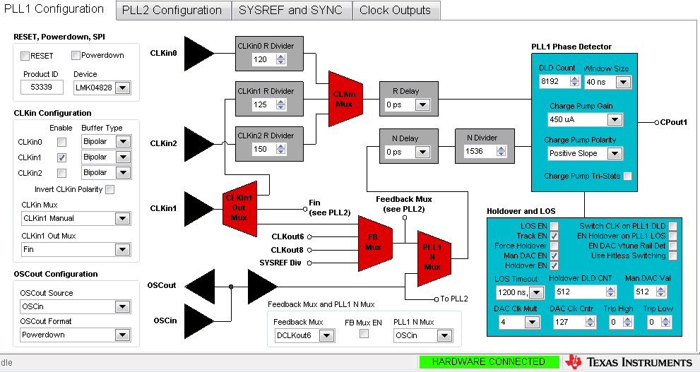
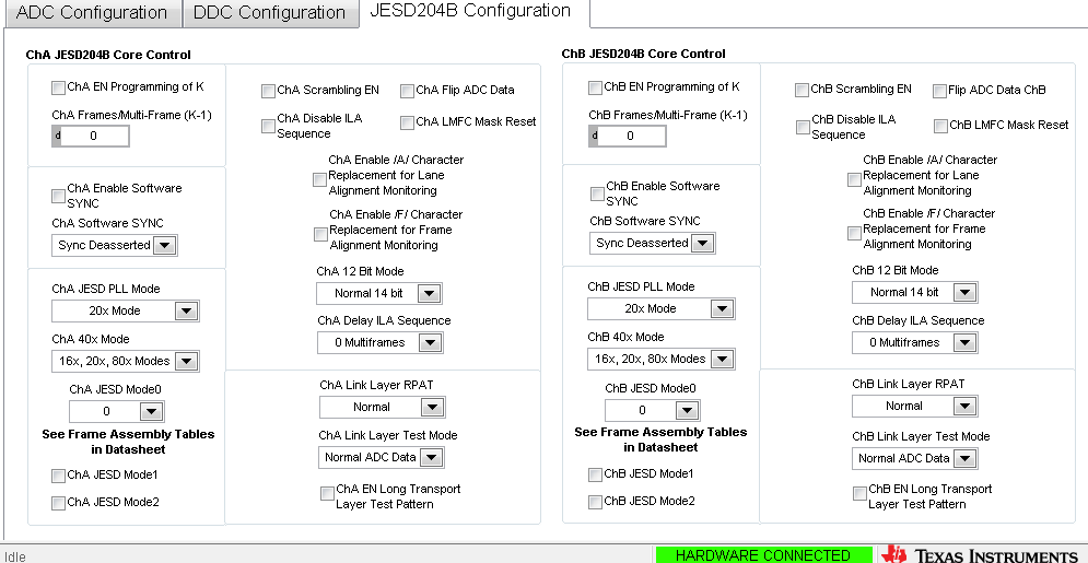
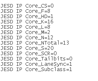
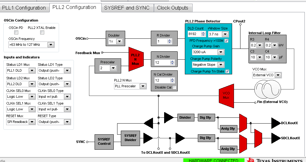
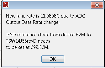
When I attempt to sample at 3GHz with a 12bit resolution I get a timeout error in HSDC. I have configured my ADC per the instructions outlined in the user manual for an externally clocked ADC using the included config files.

I notice after trying to capture data my debug LED D3 extinguished, while D8 remains solid, D1 is blinking, and the rest are extinguished. 

Can anyone provide any input on this issue?

Thanks!

  • LMFS = 82820 (verified .ini file) in 14J56revD Details folder of HSDC.

    What is the SYSREF Divider setting in the ADC Gui need to be for these settings?
  • Marshall,

    Someone will be getting back to you on the ADC GUI settings shortyly.

    Ken

  • I did not notice earlier, but in the setup I am loosing SPI only when configuring for 3G not 2G.
  • Hi,

    If you are using the right configuration files for the LMFS_82820 mode external clock, you should see a sysref divider of 640 on the LMK tab of the GUI.  (this was also mentioned in your other posting thread when you originally had the revB capture card.)

    I don't know what you mean by 'losing SPI' at 3Gsps.   Please explain.  Are you able to see that the SPI accesses to the ADC are working when clocked at 2GHz but not working when clocked at 3GHz (by clicking on some arbitrary control in the GUI and seeing that it stays 'clicked)?  And as before, I would need to see the screenshots of your HSDCPro and the relevant SPI GUI tabs to see what is going on.   What revision of HSDCPro are you using?   I believe there is a new version of HSDCPro just appearing on the TI web, but I haven't installed it in the lab yet as I have been on travel.   The new HSDCPro 4.20 should have all the files in place for your operation.  if you are using earlier HSDCPro you may need a file or two from me to copy in to your install but the screenshots should tell me that.  I would be looking for a firmware name of TSW14J56REVD_AEQ_FIRMWARE showing up in your HSDCPro screenshot.

    Regards,

    Richard P.

  • Hey Richard,

    Yes I am using the LMFS_82820 mode external clock config files and see a sysref dividers is at 640.

    By loosing SPI I mean, when I have my clock sources at 3GHz and configure the evaluation board per the user guide instructions, I can no longer set controls in the GUI/

    I am using the newest version of HSDC. I will post screenshots in my following post.
  • I have been able to get a few FFT plots at 3Gsps. It has been very hard to get the ADC configured correctly though. Almost 90% of the time after writing the ADC config file, then reading back the registers over SPI I obtain the results below and I am not able to change any controls in the GUI. My filtered clock sources are @ 3GHz at +15dBm and my analog in is at 1.75GHz at +5dBm. I am very disappointed in the performance of the eval board and SW so far as I have been not been able to adequately obtain performance results at > 2Gsps, which is the deciding factor in my design.

    HSDC is v4.2

  • Hi,

    the screenshots for the LMK tabs look ok.  Just like they should for the config file that was to be used.  The screenshots for the ADC tab would indicate that the SPI readback is not reading back what was written.   for example, the 'K' value reads back as 0 even though the config file writes this as 16.   (it should display k-1 being 15)

    now if it were only the readback that was not working then the HSDCPro should capture anyway.  But if the SPI writes were not working either then you would just get timeout.

    There are only two conditions that I run across where the SPI accesses do not work.  One is that the clock and sysref are not present to the ADC before loading the config file for the ADC itself (including pressing the hardware reset button before loading the ADC config).   If the clock and sysref are not present first then the ADC will not be configured   And you have indicated that you are following this sequence.  The other case I had run across was if a bench supply was used for the EVM and the current limit were set too low.  There is an inrush current at the time the ADC cfg file is loaded and with too low a limit I have seen the voltage droop enough to lose the SPI configuration that had just been written.   Are you using a bench supply, and what is your current limit?  if normal current draw is a bit above 2A from the 5V bench supply, I would set a limit of 3A or more just to account for inrush current.

    Regards,

    Richard P.

  • Hey Richard,

    My clocks are present prior to configuration, and are at justifiable levels after BPF.

    I am using a +5V wall wart rated for 3A as of right now. I plan to use a lab supply later on in the evaluation process. Do you think that it would exceed 3A @ +5V  prior to ADC configuration? That seems pretty substantial?

    Thanks,

    MB

  • Metering the eval board it is consuming apx. 1.3A and sees about 200mA additional current draw during the loading of the config files. This tells me that the ps would not be the limiting factor.

  • I am capturing now a FFT plot at 2.94912G samping rate. Why am I seeing this poor of performance? I believe my JESD204B settings to be accurate since it shows the appropriate lane rate (see below).

    Can you provide any input?

  • Hi,

    I also use a 3A power brick in the lab and find that to be adequate.  So I don't think power supply droop would be the issue.  We've started shipping just power cable recently due to the difficulty in finding power bricks that meet the regulatory standards for every country we might have to ship to (and the regulations keep changing all the time), so I may be seeing more people using bench supplies.  

    The poor FFT plot looks to me to be a mismatch between the configuration files used and the silicon on the EVM.     But is the SPI still not doing a proper readback during this time?  If so, the ADC may not be properly configured even with the correct files.   I would suggest this - please tell me the markings on the top of the ADC that is on the EVM (just to make sure it is the latest silicon and that there isn't still an early silicon board that got out) and attach the two config files you are using.  Then I can power up in the lab and use the exact config files that you are using.    And then I can suggest a webex where I power up in my lab and you can watch me bring it all up, and if you wish then I could watch you bring up yours.  We have to get to the bottom of this.

    Regards,

    Richard P.

  • LMK_ADC32RF45_LMF_82820_ExtClock.cfgADC32RF4x_12bit_LMFS_82820.cfgSPI appears to be working as I am reading back the ADC settings from the ADC tab in the gui as well can set controls.
    I have attached a photo of the ADC branding below.

    Thanks!

  • Do you have any updates?
  • Hi,

    the config files match what I have on my laptop, and the lot trace code matches what I have on my EVMs.  Just to be sure, in the morning I will use may laptop in the lab to bring up the EVM (I usually use the lab PC and want to exclude any possibility that the files on that machine are different.)   Then I would suggest I launch a webex session with that setup running and we can look at the setup together.      I don't know your location, so what time would you be available normally? 

    Regards,

    Richard P.

  • Hey Richard,

    I am eastern time zone, and I am free most of tomorrow during  work hours. Can you send me your work email?

  • hi,

    if you are available, I have started a webex under the meeting number 713 089 935 named ADC32RF45 EVM GUI Debug.    I powered up an EVM on my bench, into the TSW14J56 revD, and launched the EVM SPI GUI from my laptop and the HSDCPro from my laptop.   I copied the two cfg files you posted to my laptop and used those for my configuration.   everything came right up working.    (I tried the email address you first sent yesterday but it bounced.  I'd rather not put my own email address out there publicly as well.  I am hoping you could join the webex.)

    regards,

    Richard P.