This thread has been locked.

If you have a related question, please click the "Ask a related question" button in the top right corner. The newly created question will be automatically linked to this question.

[ ADS1262/3 ] How many sensors can be connected?

Other Parts Discussed in Thread: ADS1262, TINA-TI, LM74, ADS1248, LMT01, TMP107, TMP112

[ ADS1262/3 ] How many sensors can be connected?

Hi expert,

Can you help me to understand input circuit of ADS1262/3 with several sensors?
I'm sorry that I'm not quite familiar with these sensors yet, still studying for my customer.


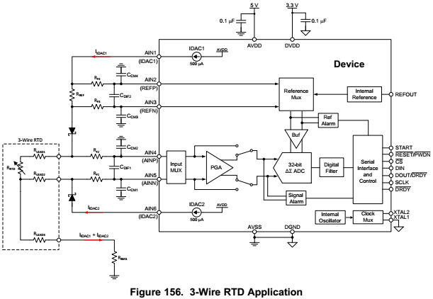
There is a drawing for 3-wire RTD application with lead wire compensation, from this, it seems that 6 analog inputs are already occupied. Does this mean only single 3-wire RTD can be connected with ADS1692/3?
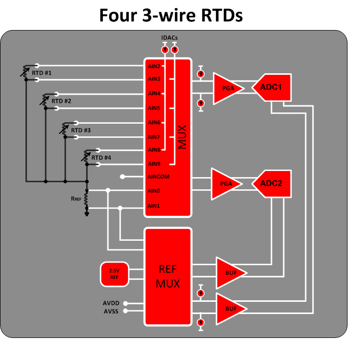
Or AIN4, AIN5 and AIN6 are dedicated for w-wire RTD-1, then AIN7, AIN8 and AIN9 can be used for RTD-2?

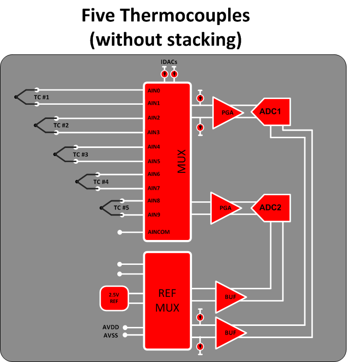
As same as above, how many thermocouples can be connected to ADS1692/3?

My customer would like to use total 12 sensors either RTD or thermocouple. What is the best solution for this?

Thank you for your support in advance.
Thanks,
Ken

  • Hi Ken,

    You can increase the number of RTDs connected to the ADC by sharing a common reference resistor and removing the dedicated IDAC current outputs (the IDAC currents can be routed through the input pins). This allows for a total of four 3-wire RTD as shown below:


    For thermocouples, you can simply use two pins per thermocouples and connect up to five thermocouples, as shown here:

    To support 12 sensors, you'll need to consider the trade-offs using either multiple ADCs or external multiplexers. Multiple ADCs would make the routing much easier. If you use external multiplexers, you could take the RTD example above and replace each RTD with a 6:2 MUX, for example.

    Best Regards,
    Chris

  • Hi Chris,

    Sorry for being late reply.
    Thanks a lot of your response, it's really helpful.

    In Four 3-wire RTDs circuit, can you please let me know what is the cycle of IDAC switching in typical application? Normally how much settling time need to be taken care?


    Also, with regards to five thermocouple configuration, do you have any ideas how CJC(Cold Junction Compensation) can be implemented?

    I'm still talking with my customer how we can support their requirement.

    Thanks,
    Ken

  • Hi Ken,

    The settling time required after switching the IDACs mostly depends on external "R" and "C" component values, including the RTD, lead, reference, filter, and parasitic values.  You could simulate it to get an idea of the order of magnitude, then it would be fairly straight forward to measure after building the circuit.

    Here is a TINA-TI template RTD circuit: 3-Wire RTD Simulation.TSC


    Measuring the cold junction can be done in many different ways (for example, with a dedicated RTD, thermistor, or IC temperature sensor). It's common to see thermistors used for CJC as they are simple and cheap, but again it depends on what level of performance you need to achieve. An RTD or IC temperature sensor could give you better accuracy. The IC temperature sensor wouldn't use up an ADC input channel, but on the other hand, some junction blocks have built-in clamps made for thru-hole RTDs.

    Best Regards,
    Chris

  • Christopher Hall said:

    Measuring the cold junction can be done in many different ways (for example, with a dedicated RTD, thermistor, or IC temperature sensor). It's common to see thermistors used for CJC as they are simple and cheap, but again it depends on what level of performance you need to achieve. An RTD or IC temperature sensor could give you better accuracy. The IC temperature sensor wouldn't use up an ADC input channel, but on the other hand, some junction blocks have built-in clamps made for thru-hole RTDs.


    Sorry, Chris, Let me double check. "IC temperature sensor" does not mean internal temp. sensor of ADS1262/63, that means some thing like LM74 kind of temperature sensor IC. Correct?

    I did misunderstand that internal temp. sensor of ADS1262/3 can be used for CJC. However, I realized that there would be an accuracy issue, and should prevent to use internal temp. sensor for CJC.

    My reference:
    ADS1248 internal temperature diode

    e2e.ti.com/.../191066

    Some hardware questions about the ADS1248
    e2e.ti.com/.../182869


    Thanks,
    Ken 

  • Hi Ken,

    Yes, by "IC temperature sensor" I was thinking of something more like LM74, but there are other more accurate options too, such as LMT01, TMP107, and TMP112. Still these are only about 0.4 deg. C accurate, so if you need even more temperature resolution than that, you would need to use an RTD.

    Similar to the ADS1248 internal temperature sensor, the ADS1262's internal temperature sensor is not fully characterized, but it is probably somewhere in the range of 5-10 deg. C accurate. It's provides a crude temperature estimate which can be used for things like: checking if the device temperature is much higher than the ambient temperature (which might be caused by an over-voltage condition) or perhaps seeing if the device temperature fluctuates significantly over a period of time (in which case the system may want to re-calibrate, for example).

    Best Regards,
    Chris