This thread has been locked.

If you have a related question, please click the "Ask a related question" button in the top right corner. The newly created question will be automatically linked to this question.

ADS8402 Overheating

Other Parts Discussed in Thread: ADS8406, THS4503

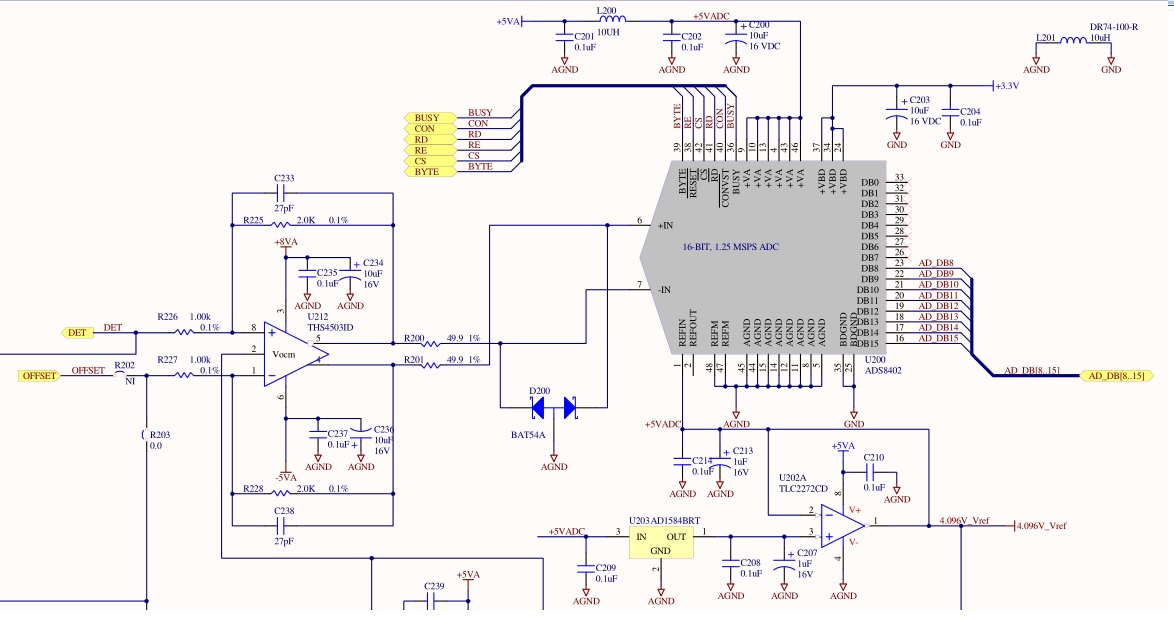
Hello, We are currently using the ADS8402IBPFBT 1.25 MSPS analog to digital converter. In our product, we use a TI TMS320C DSP and FPGA to interface with it. Occasionally, the ADC gets extremely hot (finger blistering) and I estimate that it is drawing between 0.25 and 0.5 amps from the +VA (5 volt) supply which is far too high.

In normal use the ADC converts continuously and we read a burst of data for 1-2 milliseconds about once a second. Power cycling the board seems to clear the problem. The ADC is no longer hot, and it performs conversions correctly.  Is it possible that some sequence of signals to the control logic of the ADC could result in this happening?

  • Hi Marten

    Please monitor pin voltages at VA, REFIN, REFOUT, VBD under working and non working condition. This will give us some idea about which supply pin is functioning abnormally.

    Also let us know

    1) Are you using ADS8402 internal voltage reference or you are feeding reference voltage externally.

    2) What is the voltage reference value and What is the input signal swing.

    ADS8402 is not recommended for new designs and obsolete.

    Can you check the performance with ADS8406 which is the exact equivalent of ADS8402 and has improved SNR, THD and linearity specs.

    Thanks & Regards

    Abhijeet Godbole

  • Hello Abhijeet,

    Thank you for the reply.  Yes, this is a 10 year old design, we need a few more years from this board before we can switch to a new design.

    I measured +VA to be 4.3 volts the last time I caught a hot IC.  Normally this is 4.96 volts.  Our 5V supply sagged to 4.5 volts and I used the voltage drop (0.2 V) across our filtering inductor (L200 in the schematic below, R= 0.4 to 0.8 ohm)  to estimate the current draw of 0.25 to 0.5 amps. 

    REFIN was 4.1 volts which comes from an external 4.096 V reference.  This is the same working or non-working

    VBD was 3.3 volts.  Also the same, working or non-working.

    I didn't check REFOUT, but will do that the next time I catch a hot IC.

    The input voltage is 0 to about 1 volt (single ended) to a THS4503 opamp to drive the differential input of the ADS8402.

    Thank you for the suggestion, the ADS8406 looks like I good pin compatible replacement, I will make a suggestion to our engineers.

  • I found that we actually did switch to the ADS8406 a few years ago, apparently our Bill of Materials (BOM) was not showing that.
  • Hi Marten

    Does existing board have ADS8402 or ADS8406. Does ADS8406 also heat up?

    As VA+ is drooping during heating, We need to look at the possible blocks which can make power supply droop. Can you share schematic of ADS84xx section.

    Also can you please let me know below information

    Company name:

    End application:

    Thanks & Regards

    Abhijeet

  • Hello Abhijeet,

    Thank you for the reply, sorry for the delay, I hadn't noticed the response.

    The existing board has the ADS8406.  It is the one that gets hot.  

    We just had another one get hot.  This time I measured VREF and VOUT, both were 4.12 Volts.  

    +5VA was 4.88 Volts this time, it didn't sag as much as the last time.  

    I had meant to include a schematic in my last post, it doesn't appear to have worked.  I'll try adding the file again.

    The +5VA supply is used in several places, a few opamps, a DAC904E, and a TLV5610IPW.

    I would prefer to not mention the company, but I appreciate your help with this, thank you,

    Marten

  • Hello Marten

    Thanks for the providing the details.

    Can you monitor current flowing in to VA+ pins of ADC.

    Also I could see REFIN pin net is labled as +5VADC and is also connected with 4.096V_ref. Can you please confirm if this arrangement is correct? 

    Thanks & Regards

    Abhijeet

  • Hello Abhijeet,

    Thank you for the reply.  I estimated the current draw in to the +5VA pins by measuring the voltage drop across L200.  It has a resistance between 0.4 ohms (nominal) and 0.8 ohms (max).  The two most recent occurrences of overheating showed a current draw of between 0.25 amps and 0.5 amps in one case, and between 0.11 amps and 0.23 amps in another case. 

    Yes, the +5VADC label on the 4.096 V_ref line is an incorrect label.  The 4.096 line is not connected to +5VADC. 

    Most of the time (>95%) this circuit works correctly and gives good results. Just recently one IC overheated on June 6, and then not again until June 17th.  So there seems to be something intermittent.  I would suspect a poor solder joint, but I'm not sure how that would result in excessive current draw.

    Marten

  • Hello,

    We just recently had another one overheat to the point that the chip failed.  I'm trying to determine if this could be a design issue, software issue, or soldering issue.

    Marten