This thread has been locked.

If you have a related question, please click the "Ask a related question" button in the top right corner. The newly created question will be automatically linked to this question.

[ADS1198] Programming ADS1198 using Arduino DUE

Other Parts Discussed in Thread: ADS1198, ADS1198ECGFE-PDK

Hello,
I'm very new to this but I'm trying to program a ADS1198 chip using an Arduino DUE.
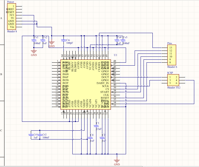
I've made a pcb layout following datasheet's page 63 instructions for a unipolar supply.
I've also grounded pins RESV1(31) and DAISY_IN(41) as it is mentioned at page 11.
I can control/read CLKSEL, DRDY, CS, START, RESET and PWDN pins using Arduino's digital pins 8-13.
I've connected Din(MOSI), Dout(MISO) and SCLK to Arduino's ICSP.

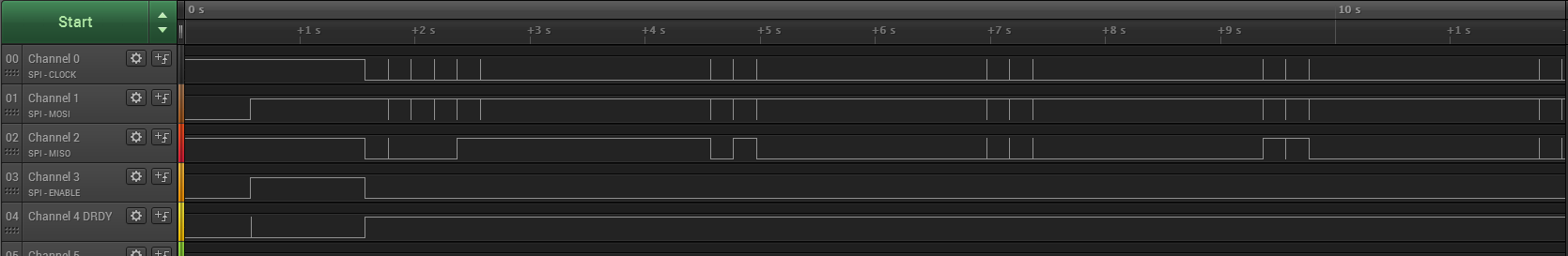
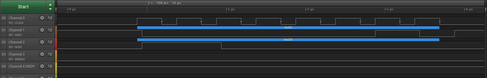
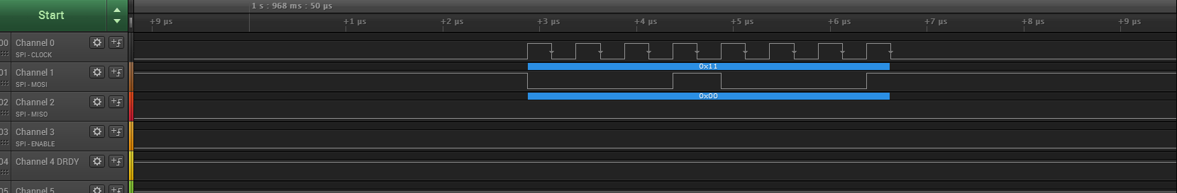
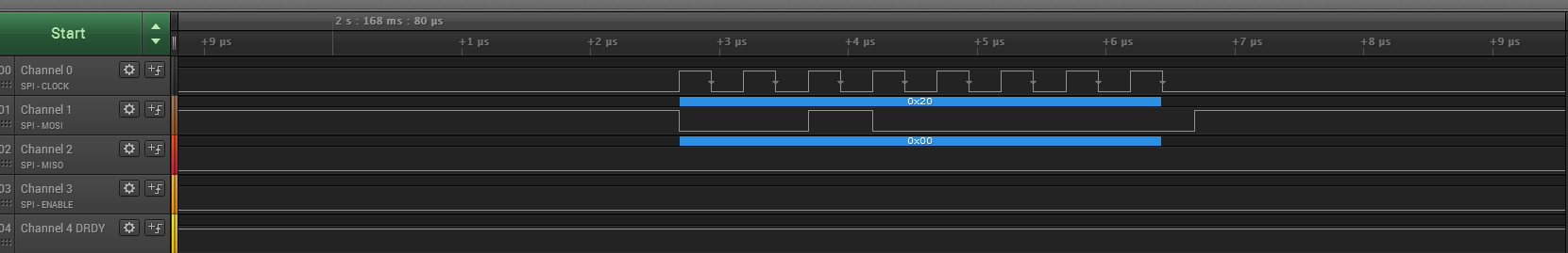
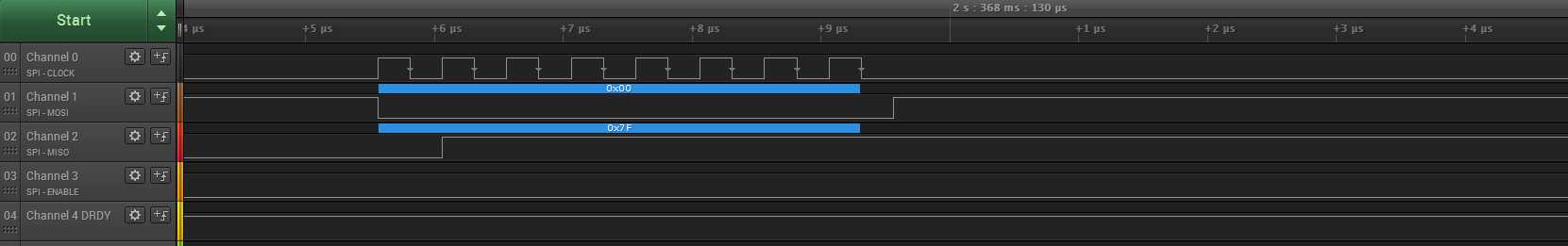
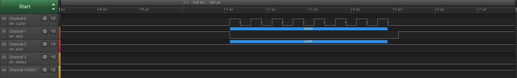
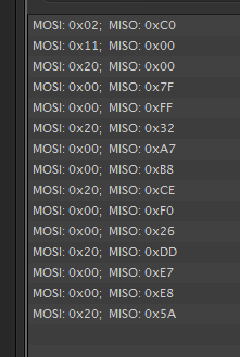
I try to communicate with the chip but checking through Arduino's serial (serial.print) I don't get what I expect.
I'm just trying to read some registers so I can ensure proper communication.

I put PWRDN and RESET pins HIGH, I begin SPI and CS pin LOW, send a WAKEUP command just to be sure, then a SDATAC command and then try to read with RREG a CONFIG register.
I put some delays between commands just to be sure.
What I get back are just random numbers.

I have same voltage for both analog and digital supplies (3,3V) if that makes any difference.
I've tried all of them with no better results.

Thank you in advance,
Spiros

  • Spiros,

    I'm moving your post to the correct forum.

  • Hello Spiros,

    Record a register read SPI transaction with an oscillosope or logic analyzer and post the results here for me to review.

    Brian
  • Hello Brian,

    Thank you for replying. I didn't answer sooner cause I didn't have a logic analyzer.

    Below I present you my arduino code and result through the logic analyzer.

    #include "SPI.h" // necessary library
    int ss=11; // using digital pin 11 for SPI slave select
    int clksel=13;//CLKSEL->1 for internal clock
    int pwrdn=8;//active low
    int reset=9;//active low
    int start=10;
    int drdy=12;
    
    void setup() {
      Serial.begin(9600);
      Serial.setTimeout(2000);
      pinMode(ss, OUTPUT); // we use this for SS pin
      pinMode(pwrdn, OUTPUT);
      pinMode(reset, OUTPUT);
      pinMode(start, OUTPUT);
      pinMode(drdy, INPUT);
      pinMode(clksel, OUTPUT);
      SPI.setBitOrder(MSBFIRST);
      delay(200);
      digitalWrite(clksel, HIGH);
      digitalWrite(pwrdn, LOW);
      digitalWrite(reset, LOW);
      delay(1000);
      digitalWrite(pwrdn, HIGH);
      digitalWrite(reset, HIGH);
      digitalWrite(ss,HIGH);
      }
    
    void loop() {
      delay(1000); //wait 1s for Power-On Reset
      SPI.begin(); // wake up the SPI bus.
      SPI.beginTransaction(SPISettings(2000000,MSBFIRST, SPI_MODE1));
      digitalWrite(ss,LOW);
      delay(200); //wait for 18*t_clk
      Serial.print("WAKEUP: ");
      Serial.println(SPI.transfer(0x02));
      delay(200);
      Serial.print("SDATAC: ");
      Serial.println(SPI.transfer(0x11)); 
      delay(200);
    
    while(1)  {
      SPI.transfer(0b00100000);//read ID register
      delay(200);
      SPI.transfer(0);
      delay(200);1
      Serial.print("RREG ID: ");
      Serial.println(SPI.transfer(0)); 
      delay(2000);
      }
    }

    And here is what I get as a result:

    An overall preview

    The wake up command

    The SDATAC command

    And the three command for reading the register (2 commands and one 0 transfer to print)

    And the rest of the transactions

    I should mention that when I check my results through serial after some repetitions all I get back is zeros.

    Spiros

  • Hello Spiro,

    Your communications look as though they should work. Can you upload your schematic?

    Brian
  • Hello Brian,

    thank you for taking the time to help me with this,

    I could really use some help.

    Here is the schematic, sorry it is a bit messy, I only made it for my pcb layout.

    Let me remind you some connections.

    I put the capacitors as they are in datasheet's page 63 instructions for a unipolar supply.

    I've also grounded pins RESV1(31) and DAISY_IN(41) as it is mentioned at page 11.

    I can control/read CLKSEL, DRDY, CS, START, RESET and PWDN pins using Arduino's digital pins 8-13.

    I've connected Din(MOSI), Dout(MISO) and SCLK to Arduino's ICSP.

    The supply is same for the analog and the digital part 3.3V.

    Thank you, Spiros

  • Hello Spiros,

    Can you confirm the CLKSEL, PWDN, and RESET pins are all held high? If they are, please probe the following pins and report to me the voltages.

    AVDD
    AVSS
    DVDD
    GND
    VCAP1
    VCAP2
    VCAP3
    VCAP4

    Regards,
    Brian Pisani
  • Hi Brian,
    all CLKSEL, PWDN and RESET pins are HIGH.
    Below I have the voltages you requested.

    AVDD 3.335V
    AVSS 0V
    DVDD 3.335V
    GND 0V
    VCAP1 1.214V
    VCAP2 1.671V
    VCAP3 5.18V
    VCAP4 313.5mV

    Spiros
  • Hey Spiros,

    The voltage reported for VCAP4 is not what I expected. Have you tried re-flowing the solder on this board or perhaps populating another? Do you ever receive DRDY signals?

    Regards,
    Brian Pisani
  • Hi Brian,
    what should be the voltage for VCAP4? Are the rest of the voltages ok?
    This is the third board I've made for the chip. I've checked all connections and looked for short-circuits but I found nothing.
    DRDY pin is shown at the first pic of the logic analyser's results at channel 4.
    So you are convinced that I should check my board for errors?

    Regards,
    Spiros
  • Hello Spiros,

    I am expecting 1.2 V at VCAP4. Please also check VREFP. It is strange that it seems DRDY is working fine and then stops when you begin communicating with the device. This seems to indicate to me that something happens to the chip where it is no longer powered properly.

    Brian
  • Hi Brian,
    VREFP is at 40.6mV.
    According to datasheet's page 24 for internal reference it should be 2.4V. Am I correct?
    Could it be a software issue or a board issue?

    Is there any other way to test chip's functionality?

    Spiros

  • Hello Spiros,

    That may not actually be an issue. If you're not able to communicate with the device at all whatsoever, then you are also on able to enable the internal reference buffer. If that buffer is not enabled then both VREFP and VCAP4 will be floating.

    Do all of the boards you've build behave in the same way? That is to say, DRDY pulses for a while but stops after you try to communicate? I have never seen an issue like this specifically so right now my best guess is that there is some sort of solder bridge or other hardware mix-up somewhere.

    Brian
  • Hello,
    I'll send the pcb layout to a professional.
    I'll get back to you when the circuit is ready.
    Thank you for your advice.

    Spiros
  • I'm back after so much time to give an answer to this problem.

    You were right after all Brian!

    I got my professional pcb, did my soldering and now chip works fine. I can read registers and get the correct values.

    My pcb layout was based on the demostration kit ADS1198ECGFE-PDK.

    So i'm not completely sure what the problem was, if it was a pcb issue or now that I changed a bit my layout but it works.

    Here is a picture of my pcb working as an arduino shield for my convienience.

    Thank you very much for your support Brian.

    Spiros