This thread has been locked.

If you have a related question, please click the "Ask a related question" button in the top right corner. The newly created question will be automatically linked to this question.

[ADS1247] We cannot configure the ADS1247 so that IDAC1 would output current.

Other Parts Discussed in Thread: ADS1247

Dir Sir,

We have a problem about ADS1247. We cannot configure the ADS1247 so that IDAC1 would output current.
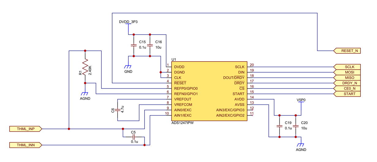
We would like to utilize ADS1247 to 2-wire RTD. So, we have designed the schematic as follows.

In the schematic, 2-wire RTD is connected to THML_INP and THML_INN.

We are planning to configure the excitation current for RTD to 1mA. So RBIAS would be configured to 2.5kohm (2.49kohm).
VREF would be configured to 2.5V.

DVDD is set to 3.3V, and AVDD is set to 5V.


The ADS1247's registers are set to the following.

address data
00h 01h
01h 00h
02h 20h
03h 00h
0ah 96h
0bh 01h


Unfortunately, it seems not to output the current from IDAC1. We have observed the voltage of RBIAS, but the voltage of RBIS is almost 0V.

We have a question about this. Are our schematic and ADS1247's settings correct?

Is there the required sequence for the setting of registers?

Best Regards,

Yuichi Tanaka

  • Tanaka-san,


    From the schematic, I noticed that the VREFCOM needs to be connected to GND. In this schematic, the VREFCOM is floating. In the datasheet it states that VREFCOM should be connected to an AC ground node through a resistance of less than 10Ω. Once this is connected I would verify that there is a reference voltage measuring the voltage from VREFOUT to VREFCOM. If the voltage isn't 2.048V, check the VREFCON[1:0] bits in the MUX1 register to make sure the internal reference is always on. The internal reference is required to operate the IDACs.

    In general, it looks as if you have made the correct connections. It also looks as if the VREFCON bits are set correctly. I would note that it seems you would have too much current going to the RBIAS if it were operating correctly. Right now the IDAC is set to 1mA. One IDAC current goes through AIN1, driving the RTD and R1 (RBIAS). The second RTD goes to AIN0, bypassing the RTD, but still going to R1. In this case you would have 2mA driving R1. I think you want one IDAC going to AIN1, but the second IDAC to go to a dead connection (like AIN2).

    There isn't a required sequence to set the registers, but I would read back the registers to make sure that the device understood the commands. If you are unsure about the communications, I would use an oscilloscope or logic analyzer to review the signals. If you can, post the results back and we can review them.


    Joseph Wu

  • Dear Wu-san,

    Thank you for your kindly reply.
    We connected VREFCOM to GND and confirmed that ADS1247's IDAC1 perform as expected.

    Moreover we have found that too much current goes to the RBIAS in this case.
    When we use the first IDAC, we will set the second IDAC to a dead connection.

    Thank you again for your reply.

    Yuichi Tanaka
  • Tanaka-san,


    I'm glad that you were able to get the IDAC to work.

    There is another option for the second IDAC. Instead of routing the IDAC to the dead connection, you can simply turn it off by disconnecting it. Writing 11xx to the four bits (in IDAC Control Register 1), the IDAC will disconnect it and turn it off.

    If you have any more questions, please feel free to post back.


    Joseph Wu