This thread has been locked.

If you have a related question, please click the "Ask a related question" button in the top right corner. The newly created question will be automatically linked to this question.

ADS52J90EVM HMC-DAQ About GUI

Other Parts Discussed in Thread: ADS52J90EVM, LMK04826

Hi,

My customer is using ADS52J90EVM with TSW14J56EVM.
He has saome questions about HMC-DAQ GUI.
Could you answer the following question, please?

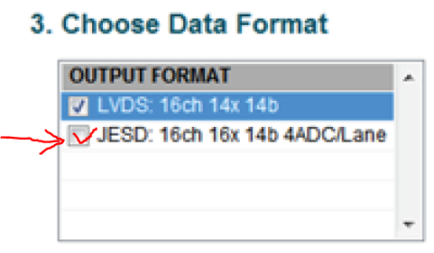
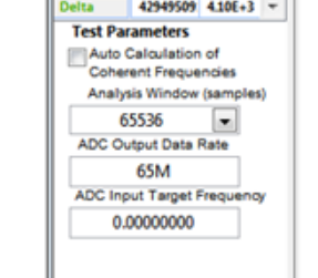
Q1: What does the below picture window mean at JESD204B interface?
-> For example, What is ADC Output Data rate?


Q2: Could you please give me User's Guide at JESD204B interface of HMC-DAQ with ADS52J90EVM and TSW14J56EVM?


Best regards,
Shimizu

  • Shimizu-san,

    Q1: This window does not have much JESD information. "ADC Output Data Rate" simply means the ADC sampling frequency and does not represent the actual output data line rate. Under the menu item "instrument options" > "Dynamic Configuration" can give you some JESD information.

    Q2: We only have the Quick Start menu for JESD configurability. You can easiliy load your own custom configuration file using the menu item at the top left. The "scripts" folder in the HMC-DAQ directory has some advanced JESD scripts. Otherwise, please contact us directly if there is a specific function that you need help with.

    Thanks,

    Chuck Smyth
  • Hi Masahiko,

    How are you?

    For Q1,

    more detail, it is Output Data Rate = Sample Clock Rate

    For Q2,

    On the user's guide, on Page 21 (also page 24)

    Please check on JESD mode option:

    Shown as below:

    Thanks and best regards,

    Chen

  • Hi Chuck,

    Thank you for previous support.
    My cusotmer wants to use ADS52J90EVM and TSW14J56 at below conditon.
    I have question and request.
    Could you answer below, please?

    Qestion:
    .cfg file in HMC-DAQ GUI has "20X" which is the end of file name.
    I think that this means MIF parameter.
    MIF is important for GTX frequency.

    Q1: Is it possible changing MIF value?
    Customer wants to change MIF value to more large.
    For the other way, Customer wants to use small GTX value.

    Q2: Can user select any MIF value?

    Q3: By what does MIF limit? JESD204B rule? or FPGA IP rule?


    Request:
    Is it possible that you make .cfg file of below conditions?

    ================================================
    [Condition 1]
    Device clk(Sampling clk):80MHz
    SYSREF(LMFC):20MHz
    Ch=16
    N'=N=12
    K=4
    F=6
    L=4
    M=16

    [Condition 2]
    Device clk(Sampling clk):100MHz
    SYSREF(LMFC):25MHz
    Ch=16
    N'=12
    N=10
    K=4
    F=6
    L=4
    M=16
    ===============================================

    Best regards,
    Shimizu
  • Shimizu,

    Yes, 20x is the MIF value.  Under 

    C:\Program Files (x86)\Texas Instruments\High Speed Data Converter Pro\14J56revD Details\MIF Files

    , you can see the supported values of the TSW EVM.  Additionally, You will need to change the ini file parameter found here

    C:\Program Files (x86)\Texas Instruments\High Speed Data Converter Pro\14J56revD Details\ADC files

    Change the two parameters belows and consult the other ini files to find the correct Fabric PLL value, for instance 40x mif should be 0x080202

    MIF Config= 0.5G to 8.0G:RX:RX_PMA_x20 
    \\List of Lane Rate Range,PLL Type and their MIF File names that needs to be configured,separated by ":"
    \\These MIF Files need to be present under MIF Files Folder
    Fabric PLL Counter = 0.5G to 8.0G:0x080404

    Then, press F10 when using the HMC-DAQ GUI.  Using the Clock Outputs page and the sysref page, configure the correct clock ratio.  I believe Ch0 DCLK divider is GTX and CH2 is the ADC_CLK.  This ratio will change with different MIFs. 

    Condition 1 is already consistent with the Quick Setup Preset for 12x,12b mode and external clock source.  This requires a 240MHz GTX for 20x MIF.

    Condition 2 is simply N=10 and change the ext clock source, right?

    Save your customer cfg with the save configuration button in the top left.  Then modify the cfg to your liking.

    TI Healthtech 16 channel AFE JESD204B Training.pdf

    For 16ch mode, Clock Ratio is always GTX/Fs = (20/MIF) *N'/L

  • Hi Chuck,

    Thank you for your support.

    I and my customer tried changing MIF with your advice.
    But EVM could not match with their condition.
    Lane Rate is "F*Fs*10" = "6*80*10" = 4.8Gbps
    GTX is "Lane Rate / MIF" = 120MHz
    then, FSDIV = 120MHz / 80MHz = 1.5
    It can not select 1.5 on HMC-DAQ GUI

    Q1: Can we set FSDIV=1.5 at HMC-DAQ GUI?
    I think that LMK04826 can output 80MHz and 40MHz from 120MHz.
    But it can not do it on this EVM
    Is it correct?

    Q2: This EVM can select MIF from 10, 20 and 40.
    What decides about MIF number limitation? JESD204B rule, FPGA limitation or user system?
    =>If MIF can use over 40 by changing FPGA source by user, I tell customer to make FPGA source by themselves at their board.

    Q3: What is GTX?
    -> EVM rule? JESD204B rule? FPGA IP rule?

    Best regards,
    Shimizu
  • Shimizu,

    Q1: No, there is no fractional divider.  You will need to use a 240 MHz clock and then divide down, it seems.

    Q2: This is from the Altera IP limitation.

    Q3: This is an FPGA rule, but it is similar on Xilinx and Altera. 

    Thanks,

    Chuck

  • Hi Chuck,

    Thank you for your reply.
    About Q1, I understand that LMK0426 on EVM can not generate 80MHz and 20MHz frequency from 120MHz.

    Best regards,
    Shimizu
  • Hi Chuck,

    I add questions.

    Q1: What ellipsis character is GTX and MIF?

    Q2: How does GTX use inside FPGA?
    -> FPGA operation clock?

    Best regards,
    Shimizu
  • Hi Chuck,

    How is the progress?

    Best regards,
    Shimizu
  • Hi Chuck,

    How is the progress?

    Best regards,
    Shimizu