This thread has been locked.

If you have a related question, please click the "Ask a related question" button in the top right corner. The newly created question will be automatically linked to this question.

ADS5263. Half frequency in sync pattern.

Other Parts Discussed in Thread: ADS5263

Dear all,

    I'm trying to calibrate the comunication with an ADS5263 ADC.  To do that I want to use the sync configuration provided by ADC.  When you use sync pattern datasheet says: All channels output a repeating pattern of 8 1s andd 8 0s instead of ADC data. Also I want sample my signal to 70MHz. Then:

     - Reset comunication. Register 0, bit 1 = 1. SPI comand 0x000001

     - Clear reset. Register 0, bit 1 = 0. SPI comand 0x000000

     - Configure ADC Data comunication to 2 wire with frame clock to 0.5x, and 16 bit serialization. SPI command 0x468801

      - Enable sync pattern. SPI command 0x450002


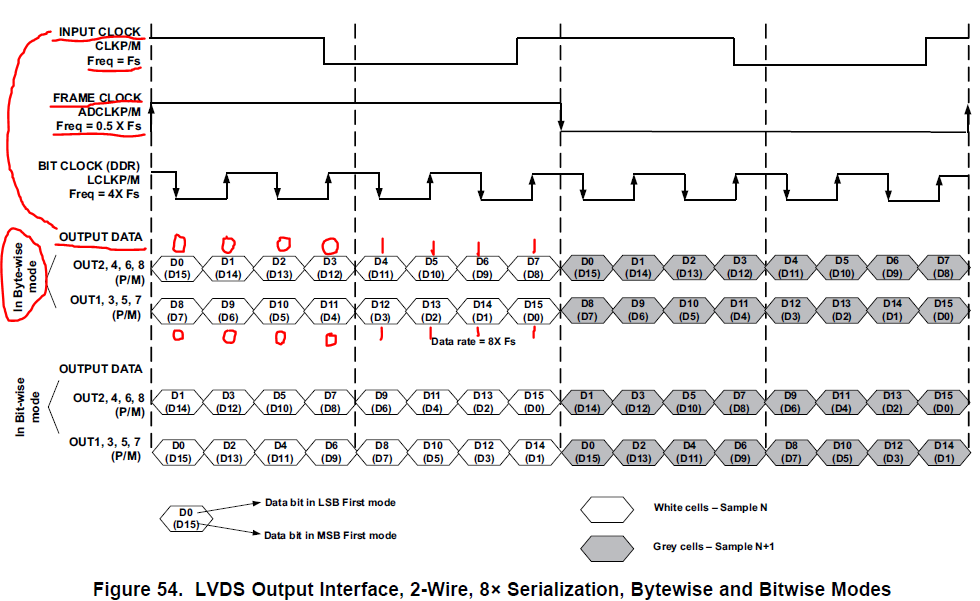
Then, with this configuration I was expecting in the data pin a square signal with 35MHz frequency (8 1s and 8 0s), like the frame clock. But I read with the scope a square signal with 70MHZ signal. To be sure that I'm not wrong with the mode that is running (bitwise, bytewise or wordwise, page 38 datasheet) I send by SPI 0x28800F. It means wordwise mode. I expect 35MHz square signal in the data ouput, but I obtain 70 MHz square signal. 


Someone knows why? Could I forgot some configuration for the ADC?


Thanks a lot for your time,

  • Juan,

    I'm assigning your post to the correct applications engineer. He should respond soon.

  • Hi Juan,

    How are you?

    Looks like your test is correct.

    When selecting 2-Wire mode (with Frame Clock = 0.5 X Input Clock = 0.5 X 70MHz = 35MHz),

    your Output Data rate (also when you are choosing SYNC Pattern=ON) will be the same speed

    as the Input Clock = 70MHz.

    Please take a look at the following diagram from ADS5263 Data Sheet:

    As you can see (8 1s = 4 1s from one data output + 4 1s from the other data output)

    also same as (8 0s = 4 0s from one data output + 4 0s from the other data output).

    So the Output Data rate = Input Clock = 70MHz.

    But Frame Clock = 0.5 * Input Clock = 35MHz.

    Hope you can see from this diagram easily.

    Thanks for using our ADS5263 EVM and TSW1400EVM.

    Thanks and best regards,

    Chen

  • Hi Juan,

    How are you?

    Hope you can understand how ADS5263 works in LVDS output.

    Thank you for using ADS5263 device.

    Best regards,

    Chen

  • Hi Chen,

      it seems that I misunderstood. I was expecting 8 ones and 8 zeros in each output. But it is in each channel.  Now it's solved. Thanks.

      By the way, do you know which is the right sequence to use bitwise mode. It easy change between bytewise and word wise. But we can not set bit wise.

    Regards,

      Juan