This thread has been locked.

If you have a related question, please click the "Ask a related question" button in the top right corner. The newly created question will be automatically linked to this question.

ADS1292R - Initialization issues

Other Parts Discussed in Thread: ADS1292R, ADS1292, ADS1292RECG-FE

Hi Experts,

i'm new to this forum and TI-devices so any help would be great! (At this point: sorry for my poor english!)

I'm currently trying to initialize an ADS1292R via SPI, following the quickstart-guide in the datasheet on page 63. After initialization the results on PIN DOUT are different to my expectations.

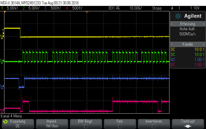
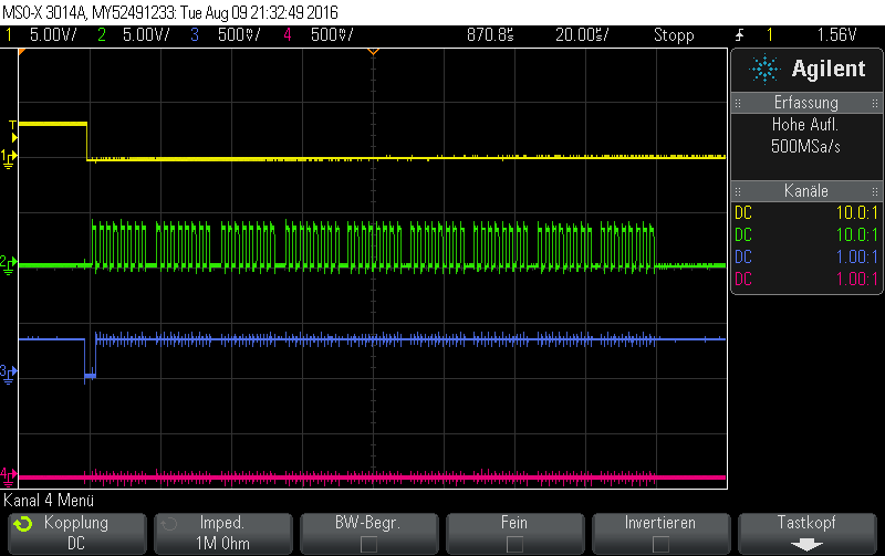
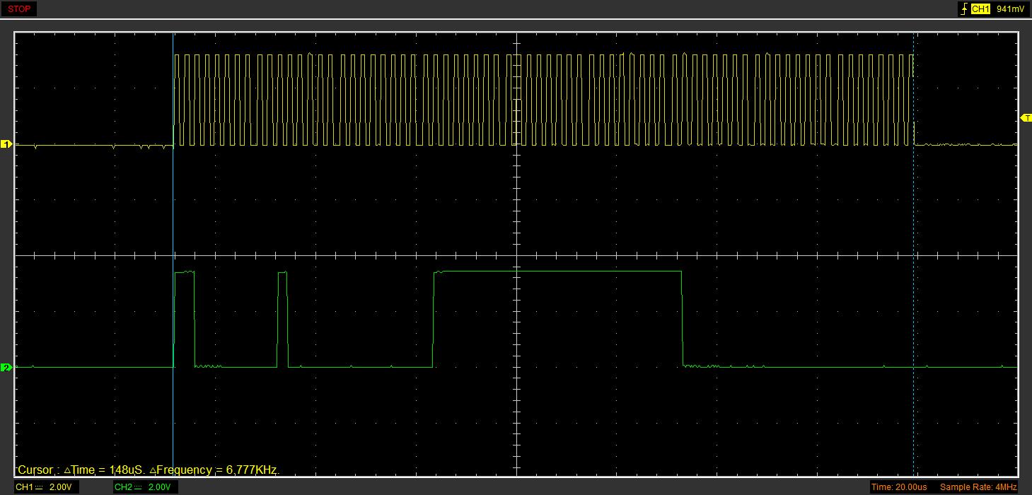
After the initialization the ADS1292R should work in RDATAC Mode. Every time DRDY goes low, the MCU shifts out 3*24Bits=72Bits (with SPI parameters: Tclk=2µs, fclk=500kHz -> Conversation_Time=72*2µs=144µs) of dummy data because otherwise the SPI Unit of the MCU will not work. So on the DOUT Pin of the ADS i would expect 24 Status Bits + 24Bits (CH1) + 24Bits (CH2) = 72Bits. However the osciloscope shows me, that the data from the ADS takes only about 102µs (From the first bit that's high to the last bit that's high). If the electrodes are touched, the Datagramm you see below DOES NOT CHANGE! If the electrodes are touched in the RDATAC MOde, i would expect wild moving bits in the last 2*24Bits.

So i think i didn't set up the ADS1292R properly in my source-code. Can anybody see major mistakes in my code below?

Picture 0: Code (main.c)

#define F_CPU 16000000
#include <avr/interrupt.h>
#include <avr/io.h>
#include <util/delay.h>


#include "mmc_config.h"	// Hier werden alle noetigen Konfigurationen vorgenommen, umbedingt anschauen !
#include "file.h"
#include "fat.h"
#include "mmc.h"		// Hardware abhaengig
#include "uart.h"		// Hardware abhaengig, es kann auch eine eigene eingebunden werden !
#include "ads1292r.h"	// Enthält Befehlssätze für den ADS1292R


// *****************************************************************************************************************
void ADS1292R_init(void){
	ADS1292R_Disable_Start();

	ADS1292R_Enable_Internal_Clk();

	ADS1292R_reset();

	ADS1292R_SDATAC();


	ADS1292R_WREG(REG_CONFIG2,0b10100000);
	ADS1292R_WREG(REG_CONFIG1,0b00000010);
	ADS1292R_WREG(REG_LOFF,0b00010000);
	ADS1292R_WREG(REG_CH1SET,0b00000101);
	ADS1292R_WREG(REG_CH2SET,0b00000000);
	ADS1292R_WREG(REG_RLDSENS,0b00101100);
	ADS1292R_WREG(REG_LOFFSENS,0x00);
	ADS1292R_WREG(REG_RESP1,0b11110010);
	ADS1292R_WREG(REG_RESP2,0b00000011);
	
	
	ADS1292R_Enable_Start();
	ADS1292R_START();
	ADS1292R_RDATAC();
	
} 

//Hardware-Commands
// *****************************************************************************************************************
void ADS1292R_reset(void){
	PORTC |= ( 1 << PC2);						//PWDN/RESET auf high, damit Reset ausgeschlossen ist
	_delay_ms(1000);
	PORTC &= ~( 1 << PC2);						//PWDN/RESET LOW -> Reset
	_delay_ms(10);
	PORTC |= ( 1 << PC2);						//PWDN/RESET auf high, damit Reset ausgeschlossen ist	
}

void ADS1292R_Enable_Internal_Clk(void){
	PORTC |=(1<<PC1);							//CLK_SEL auf 1 = internen Oszillator verwenden
	_delay_ms(1);
	
}

void ADS1292R_Enable_Start(void){
	PORTC |=(1<<PC3);							//START auf HIGH
	_delay_ms(1);
	
}

void ADS1292R_Disable_Start(void){
	PORTC &= ~( 1 << PC3);						//START auf LOW
	_delay_ms(1);
	
}

void ADS1292R_Spi_Select(void){
	DDRB |= (1<< PB0)|(1<< PB0);							//PORT B PIN 0 als Ausgang definieren
	PORTB &= ~( 1 << PB0);						//CS' auf low für SPI communication
	_delay_ms(1);
	
}

void ADS1292R_Spi_Deselect(void){
	DDRB |= (1<< PB0)|(1<< PB0);							//PORT B PIN 0 als Ausgang definieren
	PORTB |= ( 1 << PB0);						//CS' auf low für SPI communication
	_delay_ms(1);
	
}

//Software-Commands
// *****************************************************************************************************************
void ADS1292R_SDATAC(void)
{
	ADS1292R_Spi_Select();
	SPDR = 0x11;					// Send 0x11 to the ADS1x9x
	while(!(SPSR & (1<<SPIF)));;
	_delay_ms(1);
	ADS1292R_Spi_Deselect();
}

void ADS1292R_RDATAC(void)
{
	ADS1292R_Spi_Select();
	SPDR = RDATAC;					// Send 0x11 to the ADS1x9x
	while(!(SPSR & (1<<SPIF)));;
	_delay_ms(1);
	ADS1292R_Spi_Deselect();
}

void ADS1292R_RDATA(void)
{
	ADS1292R_Spi_Select();
	SPDR = 0x12;					
	while(!(SPSR & (1<<SPIF)));;
}

void ADS1292R_START(void)
{
	ADS1292R_Spi_Select();
	SPDR = START;					// Send 0x11 to the ADS1x9x
	while(!(SPSR & (1<<SPIF)));;
	_delay_ms(1);
	ADS1292R_Spi_Deselect();
}

void ADS1292R_STOP(void)
{
	ADS1292R_Spi_Select();
	SPDR = STOP;					// Send 0x11 to the ADS1x9x
	while(!(SPSR & (1<<SPIF)));;
	_delay_ms(1);
	ADS1292R_Spi_Deselect();
}

void ADS1292R_WREG(uint8_t Adresse, uint8_t Daten)
{
	ADS1292R_Spi_Select();
	SPDR = (WREG||Adresse);					
	while(!(SPSR & (1<<SPIF)));;
	
		SPDR = 0x01;					// Send 0x11 to the ADS1x9x
		while(!(SPSR & (1<<SPIF)));;
			SPDR = Daten;					// Send 0x11 to the ADS1x9x
			while(!(SPSR & (1<<SPIF)));;
	_delay_ms(1);
	ADS1292R_Spi_Deselect();
}

//SPI-Configuration
// *****************************************************************************************************************
static void SPI_init(){
	/* Set MOSI ans SCK Output, all others Input*/
	DDRB |= (1<<DDB5)|(1<<DDB7)|(1<<DDB4);		//5->MOSI, 7->CLK, 4->SS
	/* Enable SPI, Master, set clock rate fck/32 */
	SPCR = 0x00;
	SPCR = (1<<SPE)|(1<<MSTR)|(1<<SPR1)|(1<<SPR1)|(1<<CPHA);
	SPSR = (1<<SPI2X);
}

//Main
// *****************************************************************************************************************
int main(void){
	//Ein- und Ausgänge definieren
	//********* PORT A ***********
	//not used

	//********* PORT B ***********
	//not used
	
	//********* PORT C ***********
	DDRC=0x00;
	DDRC = (1 << DDC3)|(1<<DDC1)|(1<<DDC2);		//PORT C PIN 1,2,3 als Ausgänge definieren
	
	//********* PORT D ***********
	//not used
	
	
	// uart config *****************************************************
	uinit();
	uputs((uint8_t*)"\nBoot");
	
	// SPI config  *****************************************************
	SPI_init();
	
	// ADS config  *****************************************************
	ADS1292R_init();


	ADS1292R_Spi_Select();
	ADS1292R_Enable_Start();
	
	while (1)
	{	
		if ((PINC&0x01)==0)
		{
			uint8_t n=0;
			for (n=0;n<9;n++)
			{	
				SPDR = 0b00000000;                // Start transmission
				while(!(SPSR & (1<<SPIF)));
			}
		
		} 
				
		// 3x24Bit von ADS einlesen

	}
	return;

}

Picture 0.5: Code (ads1292r.h)

#ifndef ads1292r_h
#define ads1292r_h


#define CONFIG_SPI_MASTER_DUMMY   0xFF

// Register Read Commands
#define  RREG    0x20		//Read n nnnn registers starting at address r rrrr
                                //first byte 001r rrrr (2xh)(2) - second byte 000n nnnn(2)
#define WREG    0x40		//Write n nnnn registers starting at address r rrrr
                                //first byte 010r rrrr (2xh)(2) - second byte 000n nnnn(2)

#define START		0x08		//Start/restart (synchronize) conversions
#define STOP		0x0A		//Stop conversion
#define RDATAC      0x10		//Enable Read Data Continuous mode. 

//This mode is the default mode at power-up.
#define SDATAC		0x11		//Stop Read Data Continuously mode
#define RDATA		0x12		//Read data by command; supports multiple read back.

//Pin declartion the other you need are controlled by the SPI library
const int ADS1292_DRDY_PIN = 6;
const int ADS1292_CS_PIN = 7;
const int ADS1292_START_PIN = 5;
const int ADS1292_PWDN_PIN = 4;

//register address
#define REG_ID			0x00
#define REG_CONFIG1		0x01
#define REG_CONFIG2		0x02
#define REG_LOFF		0x03
#define REG_CH1SET		0x04
#define REG_CH2SET		0x05
#define REG_RLDSENS		0x06
#define REG_LOFFSENS    0x07
#define REG_LOFFSTAT    0x08
#define REG_RESP1	    0x09
#define REG_RESP2	    0x0A


#endif

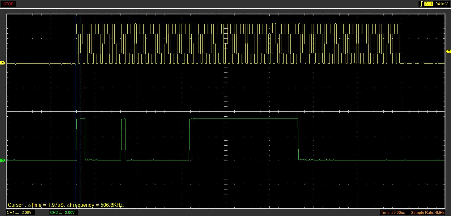
Picture 1  CH1: SPI-Clock   CH2: Pin DOUT from the ADS1292R   CURSOR: Shows the Length of the Data Burst (148µs)

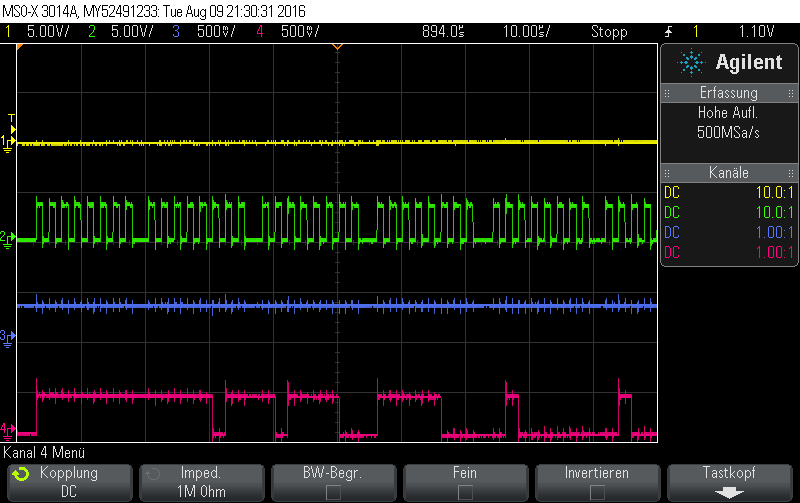
Picture 2:   CH1: SPI-Clock   CH2: Pin DOUT from the ADS1292R   CURSOR: Tclk=2µs -> fclk=500kHz

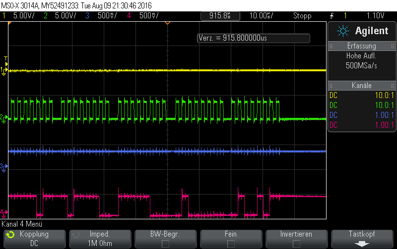
Picture 3:   CH1: SPI-Clock   CH2: Pin DOUT from the ADS1292R   CURSOR: Shows the Length of Data shifted out by the ADS1292R

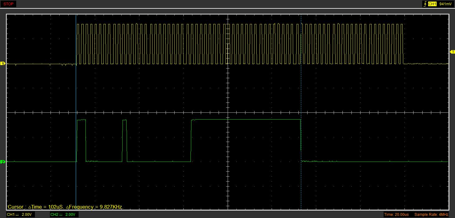
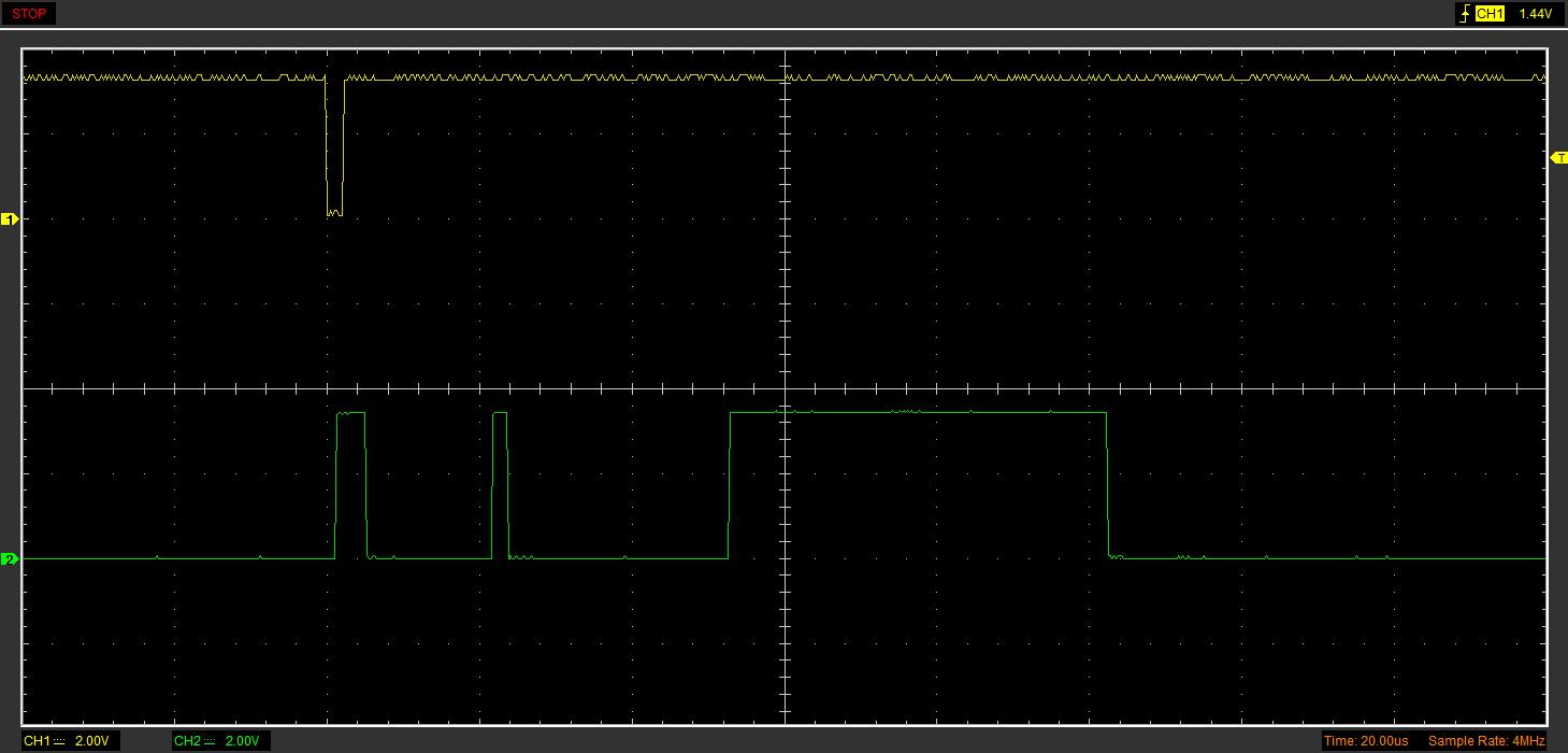
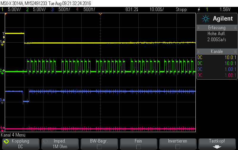
Picture 4:   CH1: DRDY Pin of the ADS1292R   CH2: Pin DOUT from the ADS1292R   CURSOR: Shows the Length of Data shifted out by the ADS1292R

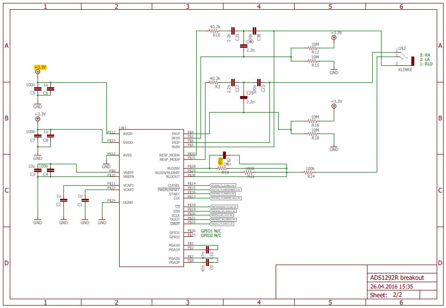
Picture 5:   Eagle-Schematic

0564.ADS1292R.pdf

Picture 6:   Quick-Start-Guide from the Datasheet

  • m k16,

    I'm moving your post to the correct forum.
  • Hi m k16!

    Welcome to the e2e forum! It looks like you've posted your ADS1292 query twice, so let's just work from this one. Can you take another scope capture showing your SCLK and DIN (rather than DOUT) and include your /CS signal?
  • Hello Tom,

    thank you for your answer! Meanwhile we managed to get serial data from the ADS1292R.

    As expected, the bits of CH1 and CH2 in the SPI Datagram are moving around when we touch the electrodes. To verify the data, we applied a triangular voltage to IN2P and IN2N, and sent it to MATLAB via UART. Unfortunately the result is a signal, in which we can hardly recognize the applied triangular voltage signal. There is a lot of noise and we don't have any clue where it comes from.

    In RDATAC mode the MOSI line is zero all the time since we are shifting out dummy data 0x00.

    Is there a major mistake in the schematic? Or do you we have some software problems? Didn't we set up the ADS properly? Any tips are welcome!

    Input:

    Scope Capture1:

    CH1: /CS CH2: SCLK CH3: DRDY CH4: MISO


    Scope Capture 2:

    CH1: /CS CH2: SCLK CH3: DRDY CH4: MOSI


    Matlab-Visualization:


    Schematic:

    6366.ADS1292R.pdf

    Code:

    #define F_CPU 16000000
    #include <avr/interrupt.h>
    #include <avr/io.h>
    #include <util/delay.h>
    #include <stdlib.h>
    #include <stdio.h>
    
    
    #include "mmc_config.h"	// Hier werden alle noetigen Konfigurationen vorgenommen, umbedingt anschauen !
    #include "file.h"
    #include "fat.h"
    #include "mmc.h"		// Hardware abhaengig
    #include "uart.h"		// Hardware abhaengig, es kann auch eine eigene eingebunden werden !
    #include "ads1292r.h"	// Enthält Befehlssätze für den ADS1292R
    
    
    // prototypen von funktionen in dieser datei
    static void timer1_init(void);


    // timer0 einstellungen, werte mit www.avrcalc.com/download.html berechnet!
    // aus diesen 3 werten ergibt sich die tick zeit, hier 10ms. 
    // 4 = prescaler 256, 3 = prescaler 64, 5 = prescaler 1024, 2 = prescaler 8. wenn prescaler 0 = prescaler dann stoppt der timer
    #if(F_CPU == 4000000)			// error 0.16%
    	#define TOP_OCR 0x9B
    	#define START_TCNT 0x64
    	#define PRESCALER 0x04
    #endif
    
    #if(F_CPU == 8000000)			// error 0,16%
    	#define TOP_OCR 0x4D
    	#define START_TCNT 0xB2
    	#define PRESCALER 0x05
    #endif
    
    #if(F_CPU == 10000000)			// error 0.351%
    	#define TOP_OCR 0x61
    	#define START_TCNT 0x9E
    	#define PRESCALER 0x05
    #endif
    
    #if(F_CPU == 12000000)			// error 0.16%
    	#define TOP_OCR 0x74
    	#define START_TCNT 0x8B
    	#define PRESCALER 0x05
    #endif
    
    #if(F_CPU == 16000000)			// error 0,16%
    	#define TOP_OCR 0x9B
    	#define START_TCNT 0x64
    	#define PRESCALER 0x05
    #endif
    
    #if(F_CPU == 20000000)			// error 0.16%
    	#define TOP_OCR 0x4D
    	#define START_TCNT 0xB2
    	#define PRESCALER 0x04
    #endif


    // timer0 variable
    volatile uint8_t 	TimingDelay;	// fuer mmc.c
    volatile uint8_t 	k=0;	// fuer mmc.c
    volatile uint8_t	i=0;
    
    
    //Timer-1 ISR mit Lebensüberwachung
    // *****************************************************************************************************************
    
    ISR (TIMER1_COMPA_vect)
    {
    	TimingDelay = (TimingDelay==0) ? 0 : TimingDelay-1;
    	if (k==100)
    	{
    	PORTD ^= ( 1 << PD5);	//Toggle PD5
    	//PORTB ^= ( 1 << PB0);  
    	k=0;
    	}
    	i++;
    	k++;
    }


    // *****************************************************************************************************************
    static void timer1_init(){
    
    	TimingDelay = 0;		// initialisierung der zaehl variable
    		
    	TCCR1B = (PRESCALER | 0b00001000);		// wenn prescaler gesetzt wird, lauft timer los	
    	//TCCR1B |= (1<<WGM12)		// timer0 im ctc mode. ACHTUNG: es muss darauf geachtet werden, dass jetzt nicht der vorher eingestellte Prescaler mitgeändert wird!
    	TIMSK = (1<<OCIE1A);	// compare interrupt channel A an
    	OCR1A = TOP_OCR;		// maximum bis wo gezaehlt wird bevor compare match	
    
    	sei();					// interrupts anschalten, wegen compare match
    	
    	DDRD = (1 << DDD5);		//EIN- und AUSGAENGE definieren (zur Lebensüberwachung/toggle von PD5) 
    }
    
    // *****************************************************************************************************************
    void ADS1292R_init(void){
    	ADS1292R_Disable_Start();
    	ADS1292R_Enable_Internal_Clk();
    	ADS1292R_reset();
    	ADS1292R_SDATAC();
    
    	ADS1292R_WREG(REG_CONFIG2,0b10100000);
    
    	//ADS1292R_Enable_Start();
    
    	
    	//ADS1292R_START();
    	//ADS1292R_STOP();


    	ADS1292R_WREG(REG_CONFIG1,0b00000010);
    	//ADS1292R_WREG(REG_CONFIG2,0b10100000);
    	ADS1292R_WREG(REG_LOFF,0b00010000);
    	ADS1292R_WREG(REG_CH1SET,0b00000101);
    	ADS1292R_WREG(REG_CH2SET,0b00100000);
    	ADS1292R_WREG(REG_RLDSENS,0b00101100);
    	ADS1292R_WREG(REG_LOFFSENS,0x00);
    	ADS1292R_WREG(REG_RESP1,0b11110010);
    	ADS1292R_WREG(REG_RESP2,0b00000011);
    	
    	ADS1292R_RDATAC();
    	//ADS1292R_Enable_Start();
    	ADS1292R_START();
    	
    	
    } 
    
    void ADS1292R_reset(void){
    	PORTC |= ( 1 << PC2);						//PWDN/RESET auf high, damit Reset ausgeschlossen ist
    	_delay_ms(1000);
    	PORTC &= ~( 1 << PC2);						//PWDN/RESET LOW -> Reset
    	_delay_ms(10);
    	PORTC |= ( 1 << PC2);						//PWDN/RESET auf high, damit Reset ausgeschlossen ist	
    }
    
    //Hardware-Commands
    void ADS1292R_Enable_Internal_Clk(void){
    	PORTC |=(1<<PC1);							//CLK_SEL auf 1 = internen Oszillator verwenden
    	_delay_ms(1);
    	
    }
    
    void ADS1292R_Enable_Start(void){
    	PORTC |=(1<<PC3);							//START auf HIGH
    	_delay_ms(1);
    	
    }
    
    void ADS1292R_Disable_Start(void){
    	PORTC &= ~( 1 << PC3);						//START auf LOW
    	_delay_ms(1);
    	
    }
    
    void ADS1292R_Spi_Select(void){
    	DDRB |= (1<< PB0);							//PORT B PIN 0 als Ausgang definieren
    	PORTB &= ~( 1 << PB0);						//CS' auf low für SPI communication
    	
    }
    
    void ADS1292R_Spi_Deselect(void){
    	//DDRB |= (1<< PB0);							//PORT B PIN 0 als Ausgang definieren
    	PORTB |= ( 1 << PB0);						//CS' auf low für SPI communication
    	
    }
    
    //Software-Commands
    void ADS1292R_SDATAC(void)
    {
    	ADS1292R_Spi_Select();
    	SPDR = 0x11;					// Send 0x11 to the ADS1x9x
    	while(!(SPSR & (1<<SPIF)));;
    	_delay_ms(1);
    	ADS1292R_Spi_Deselect();
    }
    
    void ADS1292R_RDATAC(void)
    {
    	ADS1292R_Spi_Select();
    	SPDR = RDATAC;					// Send 0x11 to the ADS1x9x
    	while(!(SPSR & (1<<SPIF)));;
    	_delay_ms(1);
    	ADS1292R_Spi_Deselect();
    }
    
    void ADS1292R_RDATA(void)
    {
    	ADS1292R_Spi_Select();
    	SPDR = 0x12;					
    	while(!(SPSR & (1<<SPIF)));;
    }
    
    void ADS1292R_START(void)
    {
    	ADS1292R_Spi_Select();
    	SPDR = START;					// Send 0x11 to the ADS1x9x
    	while(!(SPSR & (1<<SPIF)));;
    	_delay_ms(1);
    	ADS1292R_Spi_Deselect();
    }
    
    void ADS1292R_STOP(void)
    {
    	ADS1292R_Spi_Select();
    	SPDR = STOP;					// Send 0x11 to the ADS1x9x
    	while(!(SPSR & (1<<SPIF)));;
    	_delay_ms(1);
    	ADS1292R_Spi_Deselect();
    }
    
    void ADS1292R_WREG(uint8_t Adresse, uint8_t Daten)
    {
    	ADS1292R_Spi_Select();
    	SPDR = (WREG|Adresse);					
    	while(!(SPSR & (1<<SPIF)));;
    	
    		SPDR = 0x02;					// Send 0x11 to the ADS1x9x
    		while(!(SPSR & (1<<SPIF)));;
    			SPDR = Daten;					// Send 0x11 to the ADS1x9x
    			while(!(SPSR & (1<<SPIF)));;
    	_delay_ms(1);
    	ADS1292R_Spi_Deselect();
    }
    
    static void SPI_init(){
    	/* Set MOSI ans SCK Output, all others Input*/
    	DDRB |= (1<<DDB5)|(1<<DDB7)|(1<<DDB4);		//5->MOSI, 7->CLK, 4->SS
    	/* Enable SPI, Master, set clock rate fck/32 */
    	SPCR = 0x00;
    	SPCR = (1<<SPE)|(1<<MSTR)|(1<<SPR1)|(1<<SPR1)|(1<<CPHA);
    	SPSR = (1<<SPI2X);
    }
    
    // *****************************************************************************************************************
    //Zweierkomplement in float umwandeln
    float tc2f(uint32_t num){
    	float f;
    	// Prüfen ob höchstwertigstes bit gesetzt ist
    	if(num & (1<<31)){ // Wenn ja -> Zahl negativ
    		f = -1.0f * (~num + 1);
    		}else{
    		f = num;
    	}
    
    	return f;
    } 
    
    /*float tc2f(uint32_t num){
    	int32_t snum = num << 8;
    	float fnum = snum >> 8;
    	return fnum;
    } */
    
    int32_t tc2int32(uint32_t num){
    int32_t f;
    	if(num & (1<<23)){ // Wenn ja -> Zahl negativ
    		f = (0xFF000000)|(num);
    		}else{
    		f = (0x00000000)|(num);
    	}
    	return f;
    }
    
    
    // *****************************************************************************************************************
    //Zweierkomplement in signed int32 umwandeln
    int32_t tc2int(uint32_t value)	//24Bit Zweierkomplement to 32Bit int
    {
    	int32_t erg=0;				//ergebnis initialisieren
    	value=value&0x00FFFFFF;		//Eingangswert maskieren
    
    	if((value&0x00800000)==0) {	//Vorzeichenbit eins? dann liegt einen negative Zahl vor.
    		erg=value;				//Positive Zahl (Vorzeichenbit==0)
    		return erg;
    		}else{
    		value=~value;						//Negative Zahl (Vorzeichenbit==1)
    		value=value+1;
    		value=value&0x00FFFFFF;
    		erg=-value;
    		return erg;
    	}
    }
    
    // *****************************************************************************************************************
    int main(void){
    	//Ein- und Ausgänge definieren
    	//********* PORT A ***********
    	
    	//********* PORT B ***********
    	
    	//********* PORT C ***********
    	DDRC=0x00;
    	DDRC = (1 << DDC3)|(1<<DDC1)|(1<<DDC2);		//PORT C PIN 1,2,3 als Ausgänge definieren
    	DDRB=0x00;
    	
    	//********* PORT D ***********
    
    
    	//Datenpuffer für Daten vom ADS
    	uint32_t BUFF_STAT[3];
    	uint32_t BUFF_CH1[3];
    	uint32_t BUFF_CH2[3];
    
    	// timer0 config  **************************************************
    	// initialisierung, auf jeden fall vor mmc_init(), 
    	// denn da wird der timer benoetigt!
    	timer1_init();
    
    	// uart config *****************************************************
    	uinit();
    	uputs((uint8_t*)"\nBoot");
    	
    	// SPI config  *****************************************************
    	SPI_init();
    	
    	// ADS config  *****************************************************
    	ADS1292R_init();
    	
    
    	ADS1292R_Spi_Select();
    	while (1)
    	{	
    	if((PINC&(1<<PC0))==0)
    		{
    		ADS1292R_Spi_Select();
    
    		uint8_t n=0;
    		for (n=0;n<9;n++)
    			{
    				SPDR = 0b00000000;                // Start transmission
    				while(!(SPSR & (1<<SPIF)));
    				if (n==3)
    				{
    					BUFF_CH1[0]=SPDR;
    				}
    				if (n==4)
    				{
    					BUFF_CH1[1]=SPDR;
    				}
    				if (n==5)
    				{
    					BUFF_CH1[2]=SPDR;
    				}
    				if (n==6)
    				{
    					BUFF_CH2[0]=SPDR;
    				}
    				if (n==7)
    				{
    					BUFF_CH2[1]=SPDR;
    				}
    				if (n==8)
    				{
    					BUFF_CH2[3]=SPDR;
    				}
    			}
    							
    							/*
    							BUFF_CH2[0]=0xAB;
    							BUFF_CH2[1]=0xCD;
    							BUFF_CH2[2]=0xEF;
    							*/
    							uint8_t dummy=0x00;
    							int32_t erg=0x0;
    
    							/*
    							//Channel 1**************************
    							erg |= (BUFF_CH1[0]<<16);
    							erg |= (BUFF_CH1[1]<<8);
    							erg |= (BUFF_CH1[2]);
    							*/
    							
    							//Channel 2**************************
    							erg |= (BUFF_CH2[0]<<16);
    							erg |= (BUFF_CH2[1]<<8);
    							erg |= (BUFF_CH2[2]);
    							
    
    							int32_t test=tc2int(erg);
    							//test=0xABCDEF;
    						
    							dummy=test>>24;
    							uputc(dummy);
    								
    							dummy=0x00;
    							dummy=test>>16;
    							uputc(dummy);
    							dummy=0x00;
    							dummy=test>>8;
    							uputc(dummy);
    							dummy=0x00;
    							dummy=test;
    							uputc(dummy);
    							
    							//uputc(0xAB);
    							uputc(0x0D);	//CR
    							uputc(0x0A);	//LF
    							//uputc(0x00);
    		ADS1292R_Spi_Deselect();
    
    		}
    
    	}
    	return;
    
    }
    

    Tank you!


  • Hey Tom,

    to doublecheck the Connection between ADS1292R<->Microcontroller<->COM-Port<->MATLAB, we enabled the Test-Signal on CH2 and got the following plot:

    Settings of the ADS1292R are:


    I've got 2 questions:

    -The testsignal looks good, but it has an offset. Is that normal? I scaled the glitches to the reference and calculated following values: Vintf=200*(2.42V/2^23)=57.7µV Ist that a regular value? Offset would be like: Voff=1900*(2.42V/2^23)=548.12µV

    -How do i have to set the registers properly to recieve an ECG Signal on CH2 with the following schematic

    ADS1292R-SChaltplan.pdf

    Thank you!!

  • Hi m k16,

    Something looks wrong here. The output seems saturated at the ~1900 value. I would expect to see some noise there, similar to the ~3500 values. The easiest thing to do to get the ADS1292 device setup properly is to follow the flow chart on page 63 of the datasheet. After the decision point for the internal or external reference, instead of setting the channels to input short (or test), set them for 'normal electrode' by setting bits [3:0] in the CHxSET register to b000.
  • meanwhile we recieved following testsignal on CH2. It's still asymmetrical but we can see noise at both the top and the bottom value. Is the testsignal realistic or does it still look faulty to you?

    Register settings are:

    Recieved signal:

    After recieving the testsignal we changed the registersettings for real data aquisition on CH2. We changed CH2SET to b0000 0000 ([Bit 7]: Normal operation [Bit 6-4]: Gain=6 [Bit 3-0]: Normal electrode input). And CONFIG2 to b1010 0000 (INT_TEST=Off; TEST_FREQ=At DC).

    Then we applied a 0.5Hz triangular voltage with Vpp~2V to IN2P and IN2N and got the following results:

    New register settings:

    Signal on IN2P and IN2N:


    Recieved Data:


    If we don't even get a Signal with Vpp=2V properly, we'll never manage to get a Signal with less than Vpp=5mV. Do you have an Tipps? Is there a mistake in our analog-circuit?

    Thank you, Tom!! 

  • Hi m k16,

    This is the test signal that I see when I have the same register settings as you:

    Since these settings put the sample rate at 125SPS, I grabbed 1250 samples to try and match your 10 seconds of data in the first plot. What is your ‘Y’ scale and why is it so different (+0.2 to -0.5) now compared to the plot from the 12th ( +3500 to +~1900)?

  • Hi m k16 -

    One thing I forgot to mention - by your schematic, you have a uni-polar supply to the ADS1292R. The triangle wave in the screen shot you provided is bi-polar, you'll need to give that a DC offset so that it does not go negative WRT to the AVSS rail of the device. Also, you'll need to be careful about the gain setting with the amplitude of the input signal. Use G=1 for a 2Vpp input.
  • Hey Tom,

    we purchased the ADS1292RECG-FE (http://www.ti.com/tool/ads1292recg-fe) and followed the installation-Guide. Unfortunately the provided pc-application can not connect to the ADS1292R demonstration kit. The driver installation was succesful, but the device is displayed with a warning in the device-manager. What's wrong here? We used different PC's and OS(Win 10/7/XP) and rund the application as admin. The green LED is flashing.


  • Hi m K16,

    The blinking green light is normal - that at least lets you know the board is working. What shows up under the Driver Details tab? You might have to manually update the driver by clicking on the 'Update Driver' -> 'Browse my computer...' and then navigate to C:\Program Files (x86)\Texas Instruments\ADS1x9xevm\USB Drivers. Let me know if that resolves the problem.
  • Hi Tom,

    thank you for your answer. I already updated the driver manually and if i try it again, i get the message "the best driver software for your device is already installed". The Driver Details tab shows the following:

    thanks
    Marvin

  • Hi Marvin,

    Take a look at this post and let me know if that works for you:

    e2e.ti.com/.../1610010
  • Hi Tom,

    thanks for your answer. That thread does not fix the problem for me. Under Win10 i alredy disabled driver signatures, because i wasn't abled to install the driver. After disabling the driver signature, i installed the driver as it is shown in the user's guide. It finished with the following dialog.

    When I plug the board on to my (or any other) pc, the system does not show any prompt like it normally does ("device conneced" o.s.). Is that a normal behaviour?

    thank you so much, Tom

    Regards

    Marvin