This thread has been locked.

If you have a related question, please click the "Ask a related question" button in the top right corner. The newly created question will be automatically linked to this question.

Is it possible to configure the demodulator in AFE5809 to pass through ADC data to LVDS?

Other Parts Discussed in Thread: AFE5809

Hi, everyone,

I'm developing a AFE5809 + FPGA + Application SoC system.

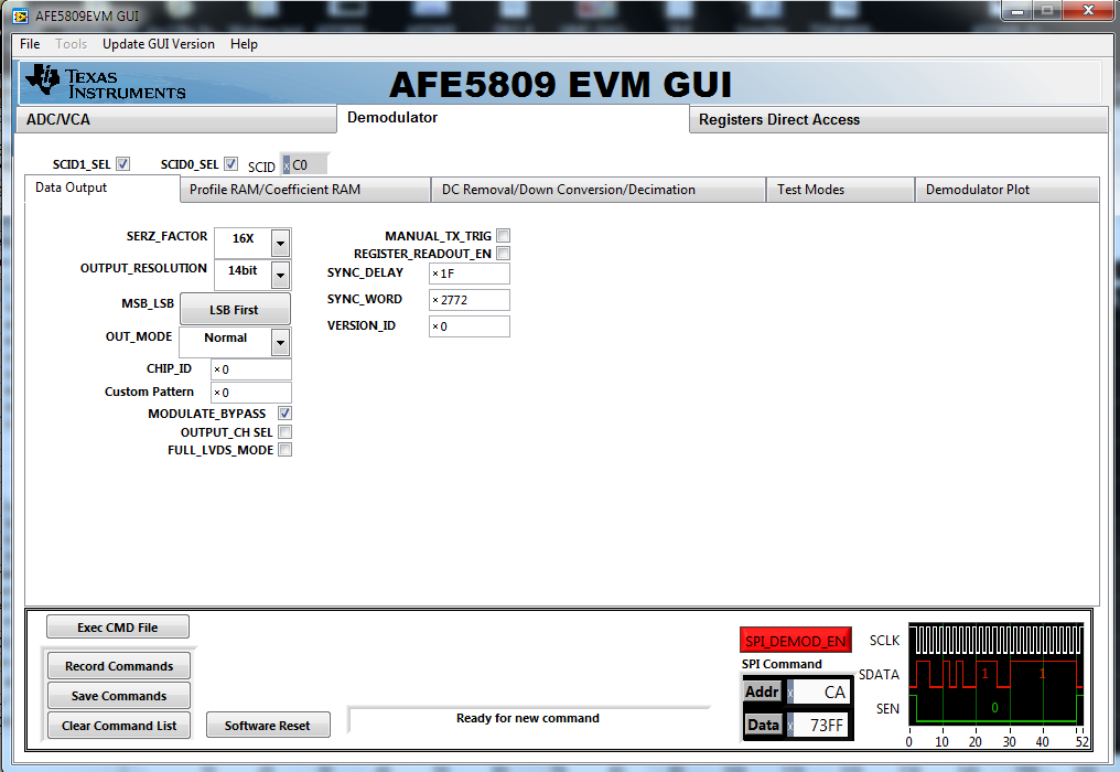
The FPGA relies on the sync word in the LVDS channels of AFE5809 to function properly so I can not turn the demodulator off.

Is it possible to leave the demodulator enabled but let it pass ADC data through?

I'm thinking about:

set M=1; MODULATE_BYPASS 0x0A[14]=0; OUTPUT_CHANNEL_SEL 0x0A[11]=0; DWN_CNV_BYPASS 0x0A[2]=1

And set coefficient ram to a single impulse, and set profile RAM to a unit gain.

then ADC data will by pass down conversion, while decimation filter and decimation do nothing.

Is this correct?

So basically what I'm asking is, when down conversion is bypassed, is the ADC data passed unchanged to the I channel while Q channel is always 0?

  • Dehuan,

    I'm assigning your post to the correct applications engineers. they should respond soon.
  • Dehuan,

    Yes, if you want to bypass the DEMOD block, but keep the sync word,  please follow this configuration:

    EN_DEMOD =0

    DC_REMOVAL_BYP, DWN_CNV_BYP, DEC_BYP = 1

    M=1

    Modulate_Byp = 0 (enable to remove the sync word)

    Output_ch_sel = 0 (ch A)

    Thanks,

    Chuck

  • Hi Dehuan,

    According to your bypass settings for DC_removal, DWN_CNV and DEC.

    there is shown on the GUI:

    Then, First:

    1) Set the DEMOD block = ON

    Then, we tested and got the result (your signal + sync word):

    2) Set the DEMOD block = OFF

    Then, we tested and got the result (your signal + NO sync word):

    This just looks like only input signal without using Demod mode.

    Thanks and best regards,

    Chen

  • Hi Dehuan,

    Here are the explanations of the setting to display Sync Word signal.

    1) Here is the AFE5809 register settings:

    2) After that when you are running TSW1400 GUI to the AFE5809 device,

    you should see the Sync Word showing including the capture data as well.

    One shows the captured data from CH3.

    The other shows the captured data from CH4.

    Thank you very much for using AFE5809 EVM and TSW1400 EVM.

    Best regards,

    Chen

  • Hello,

    I am trying to connect ADC output to FPGA for Image processing. The answer you provided will work for me as well?
    I will be getting signal from transducer which is around 200-300kHZ.
    Thank you
  • It should work, but depending on whether you need sync word or not, there are two different ways to do it.


    This question is about the case when sync word is needed for FPGA to function properly, so we need data to pass through demodulator without demodulating it.


    If you don't need sync word, you can just bypass all of the demodulator chain, which is well documented in the reference manual.

  • Hi Vatsal,

    The input signal for AFE5809 is using AC coupling method.
    Please let us confirm with our engineer to see your signal frequency from 200-300kHz range
    should be ok with those capacitor 0.1uF value can fit.
    We will let you know.

    Thanks and best regards,
    Chen
  • Hi Chen and Dehuan,

    Thank you,
  • Vatsal,

    Please see figure 59 from the datasheet.  I shows the low frequency roll-off.  INM Cap of 1uF is recommended for low-frequency applications.

    Thanks,

    Chuck Smyth