This thread has been locked.

If you have a related question, please click the "Ask a related question" button in the top right corner. The newly created question will be automatically linked to this question.

PT1000 Sensor count non-linearity

Other Parts Discussed in Thread: CD4052B

Dear Joseph,
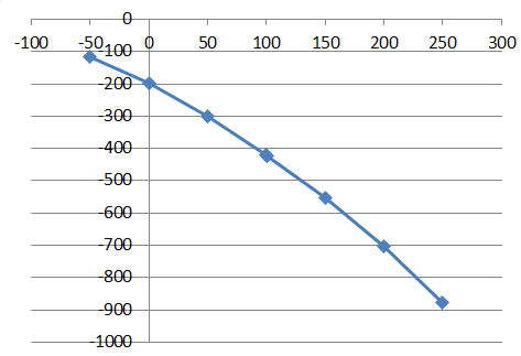
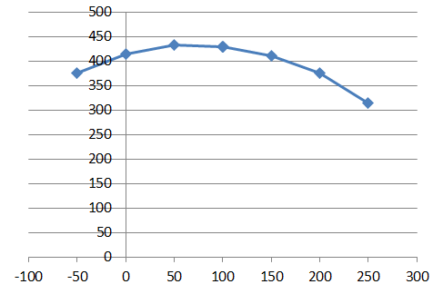
      When we increased the current source value to 0.25mA from 0.1mA, there is no count bounce issue. But we have non-linearity issue. When we used 0.25 mA current source there is count deviation (Non-linear). So my question is
1. What are the reasons for count deviation (Whether it is because of External circuit or due to current source)?
2. Please find the attached circuit for your reference and suggest me the reasons of non-linearity?

5415.PT1000_Circuit.pdf

Regards
P. Sivaram Kumar

  • Sivarama,


    Sorry for the long delay. I've been working on different projects at work, and it's been difficult keeping up with the E2E.

    Looking at your schematic, the first thing that might cause the non-linearity would be any series resistance. In your case it would be from either 249Ω resistors or the series resistance in the MUX. Since there is some input current going into the ADC, the series resistance might cause a voltage drop giving an error (either a gain error or linearity error). To test this, you may need to bypass an series resistance with the inputs.

    Another way of testing this would be to "chop" the currents so that the IDAC currents are averaged. In the normal configuration you apply IDAC1 to AIN0 and IDAC2 to AIN1. Then you would take the reading. In the second condition you reverse the IDACs so that IDAC2 goes to AIN0 and IDAC1 goes to AIN1. Then you take a second reading. The first and second readings are average to eliminate the mismatch between the IDAC currents.

    There might be some contribution from leakage as well. Although the CD4052B is supposed to be low in leakage, if you have any input protection, there may be errors associated with the leakage. Any leakage away from the RTD/reference resistor may cause some error.

    How much linearity error are you seeing? Can you show the ADC readings with a variety of RTD resistance values? It might help to tabulate the error to understand how large of an error you are seeing.


    Joseph Wu
  • Dear Joseph,
    Thanks for the reply. Please find the below table for the readings observed for PT1000 input with 0.25mA current sources activated.

    IpTemp ResPT1000 Expected Count Observed Count
    i/p   CntbyAdc/0X7FFF Practical
    -50 803.1 19493 19376
    0 1000 24272 24074
    50 1194 28981 28682
    100 1385.1 33619 33200
    101 1388.9 33712 33290
    150 1573.3 38188 37634
    200 1758.6 42685 41982
    250 1941 47113 46237


    If you observe the expected and practical counts, at -50C there is no much deviation from the expected and at 250C almost 1000 count difference is there i.e. the non linearity is increasing. If this non-linearity is due to series resistors, the same circuit is used for PT100 also. For PT100 we have used 1mA current source. Here the only change is reference resistor value, for this we didn't observed any issue. So please analyse the circuit and let me know your suggestion.

    Regards
    P. Sivaram Kumar

  • Sivarama,


    When you give me the data, I need the details on how you set up the experiment. First, what is Ip Temp? Is this the temperature of your system in some sort of oven or a calibrated source? How accurate is this?

    Second, did you get the ResPT1000 number from look up table or as a calculation? I'm assuming that the Expected Count comes from a calculation from the ResPT1000 number. It also looks as if your reference resistor is a different value that you show in the schematic. I calculate that you used a 2.7k resistor instead of an 8.2k.

    Also the Expected Count is off, and I'm not sure how you get these values. Note that the positive full scale is 2^15 not 2^16, so the maximum count should be 32767 for 7FFF. Next time explain your schematic and show your calculation. I'm assuming that you are using a ratiometric measurement, based on the RTD resistance and the reference resistor, so I'll go with that until I get a better explanation of what you're doing.

    Going back to your results and assuming that you have somehow gotten a full scale of 2^16 (65535), I'll just assume that the Observed Count is the ADC data. If you take the Observed count and subtract the Expected Count, you can see the error in the system. It's plotted in the data and graph below:

    IpTemp ResPT1000 Expected Count Observed Count Error
    i/p CntbyAdc/0X7FFF Practical
    -50 803.1 19493 19376 -117
    0 1000 24272 24074 -198
    50 1194 28981 28682 -299
    100 1385.1 33619 33200 -419
    101 1388.9 33712 33290 -422
    150 1573.3 38188 37634 -554
    200 1758.6 42685 41982 -703
    250 1941 47113 46237 -876

    You can also see that the error gets larger with the input. While there is a small amount of non-linear bow in it, it also looks like the error is primarily a gain error with an offset error added in. There's about a 100 counts of non-linearity error also.

    Let's assume the reference resistor is 2.77k instead of 2.7k, the you get this curve set of data:

    IpTemp ResPT1000 Expected Count Observed Count Error
    i/p CntbyAdc/0X7FFF Practical
    -50 803.1 19000.7 19376 375.2918412
    0 1000 23659.2 24074 414.7942238
    50 1194 28249.1 28682 432.9083032
    100 1385.1 32770.4 33200 429.6340794
    101 1388.9 32860.3 33290 429.7290975
    150 1573.3 37223.0 37634 410.9715523
    200 1758.6 41607.1 41982 374.920722
    250 1941 45922.5 46237 314.4815884

    By adjusting the reference resistor, I'm just showing that there is a gain error that is part of this measurement. Here the gain error is adjusted out by a change of 0.07k out of 2.7k or 2.6%. There's also an offset of 300 to 400 counts. Both seem like large amounts of each error. I'm not saying that the error is coming from the reference resistor. I'm just using this to show approximately how much error is part of the system. Some quick sources of error might be the gain error of the ADC (0.5% max), the mismatch error of the IDAC (0.15% typ), but neither are enough to explain the large error that you're seeing.

    If your reference resistor had an accuracy of 2%, then you might see this kind of error. Other than that, you may be losing current through some of the circuitry connected to the reference or RTD.

    Since the observed count is lower than expected, I would guess that there is current being lost that would normally go into the RTD. If the observed count was larger than expected, then I would guess there is current lost going into the reference. I'd look at any input protection diodes, or the mux to be possible sources of leakage. If you have a multimeter, or oscilloscope connected to the RTD, you may have added leakage.

    Also, if you're cycling through multiple channels, you might be short on the settling time. Since each input channel has capacitors (~0.5uF), it might take extra time as you move from channel to channel.


    Joseph Wu

  • Sivarama,


    It also occurs to me that the offset might be coming from a mismatch in the resistance seen at AIN0 and AIN1. Even if the currents match, any resistance difference seen would become an offset error. This resistance would include the 249Ω resistors used in the filters and any resistance in the CD4052B mux.

    Additionally, any resistance mismatch that changes with the input signal (similar to what the mux might do) may be seen as a gain error or non-linearity error.


    Joseph Wu