This thread has been locked.

If you have a related question, please click the "Ask a related question" button in the top right corner. The newly created question will be automatically linked to this question.

ADS1278EVM DRDY SIGNAL PROBLEM

Other Parts Discussed in Thread: ADS1278

We are interfacing an ADS1278EVM to the lcdkc6748 using SPI1 port. We are working with the MM0 as power source for the ads1278evm through the header J5 and are also using the Starterware platform wtih SPI protocol. Our clock signal (4MHz) wich is the same sclock signal comes from a signal generator, the sampling frequency is aprox 15KHz in low power mode and we are also using a GPIO port to sensing the DRDY signal and  this starts communication. DSP is in slave mode that it is because (CLCK and SCLK are always running). 

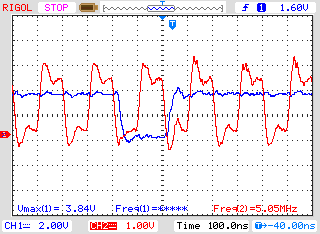
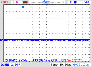
We have understood from datasheet that SCLK and DRDY signals are synchronized each other but when we see these signals in the oscilloscope we realized they don't, which is why sometimes we received streams shifted one bit to the left or right.

 Which could be our problem? Maybe any kind of hysteresis?

The resulting signals are as follows:

Fig1 and 2 DRDY Signal (blue) Vs SCLK (red)            

  • Hello Jonatan,

    The falling edge of /DRDY must occur at least 1*tCLK before the first rising edge of SCLK. This is called tDS in the SPI Format Timing Specifications table. You mentioned you are using a 4MHz clock, but the attached images show a 5MHz clock signal. This means that you must wait at least 1/5MHz = 200ns after the falling edge of /DRDY before sending SCLKs to the device. In the first image, the first rising edge of SCLK appears ~150ns after the falling edge of /DRDY. In the second image, the difference is even less. This will cause you to miss the MSB of the data word.

    If you wish to leave CLK and SCLK free-running, you must use the Frame-Sync interface instead.

    Best Regards,

  • Hi Ryan

    Thanks for you reply,

    Initially, We tried to configure the DSP as master and to synchronize them in agreement to the ADS1278 datasheet, however, we realized when there is not SCLCK signal free-running beetween 12bits transmissions, DRDY  signal looks like this:

    That is because we can not to sense falling edge of DRDY signal when a sample is ready to begin reception. In fact, when SLCK is enable-disenable, falling edge time interval DRDY goes to 1.2us when it should be aprox 357ns whit 4MHz. Secondly C6748 lcdk does not support SPI-frame sync protocol.

    How could we handle DRDY signal behaviour when SCLK is enable-disenable?

    We think other reason DRDY signal fluctuates so much is because CLCK-SCLK is not so clean. Could this to fix something?  

    Thanks for your help,

    Regards.

  • Hi Jonatan,

    Sorry, but I did not understand what you were trying to say by

    Jonatan Vanegas said:
    when there is not SCLCK signal free-running beetween 12bits transmissions, DRDY  signal looks like this:
    .

    Let's clarify the configuration in which you are using the ADS1278:

    1. Input master CLK is 4MHz
    2. Low-Power Mode
    3. SPI interface mode
    4. fDATA = 15.625kHz for CLKDIV = 0 (time between /DRDY falling edges should be 64us)

    Your processor must sense the falling edge of /DRDY, wait at least 250ns (1*tCLK), and then begin sending SCLK signals to the ADS1278. You SCLK frequency will need to be faster than 376.47kHz in order to read all 24 bits before the next /DRDY.

    Best Regards,