This thread has been locked.

If you have a related question, please click the "Ask a related question" button in the top right corner. The newly created question will be automatically linked to this question.

Sporadic DRDY low signal with ADS1278

Other Parts Discussed in Thread: ADS1278, TMS470R1B1M

I am using two ADS1278 chips in daisy chain fashion (so total 16 channels = 48 bytes) with TMS470R1B1M. I am using SPI with DRDY with SCLK = 9.6 MHz. The ADC is configured for Low Speed mode. So fClk/fData = 2560. So for 9.6 MHz I get an interrupt from DRDY every 266.67 us. I see the DRDY line pulsing low every 266.67 us. On scope I checked that the DRDY stays low for about 10 us before it goes high again. 

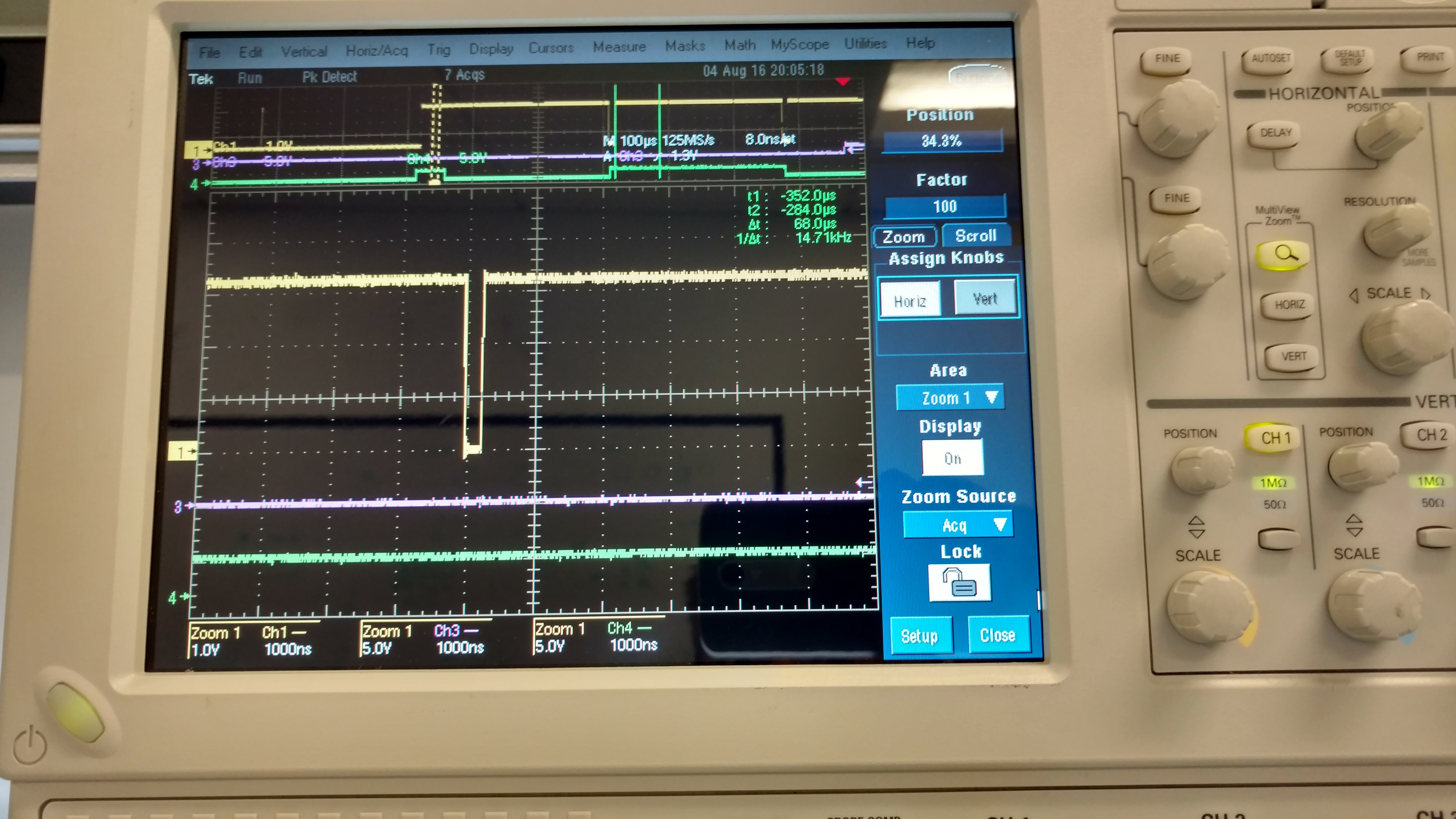
Once in a while the DRDY goes low and it generates an interrupt and I configure my DMA to fetch data over SPI. Once DRDY goes high, after some time I noticed that the DRDY goes low again sooner than expected (before the next expected 266.67 us). This time the pulse is low for only 200 ns, but this messes up my DMA as the interrupt is triggered again causing DMA to be reconfigured - while it was in middle of a transfer so now I see that my data bytes are messed up. I managed to catch this sporadic DRDY pulse on analog scope. I have attached the screenshot below. 

Any idea what could be causing this sporadic DRDY pulse. 

Screenshots:

Channel 1 (Yellow waveform at top) is DRDY. 

Channel 4 - (Green waveform at bottom) is a testpin which I toggle inside ISR triggered by DRDY. 

Good DRDY Pulse:

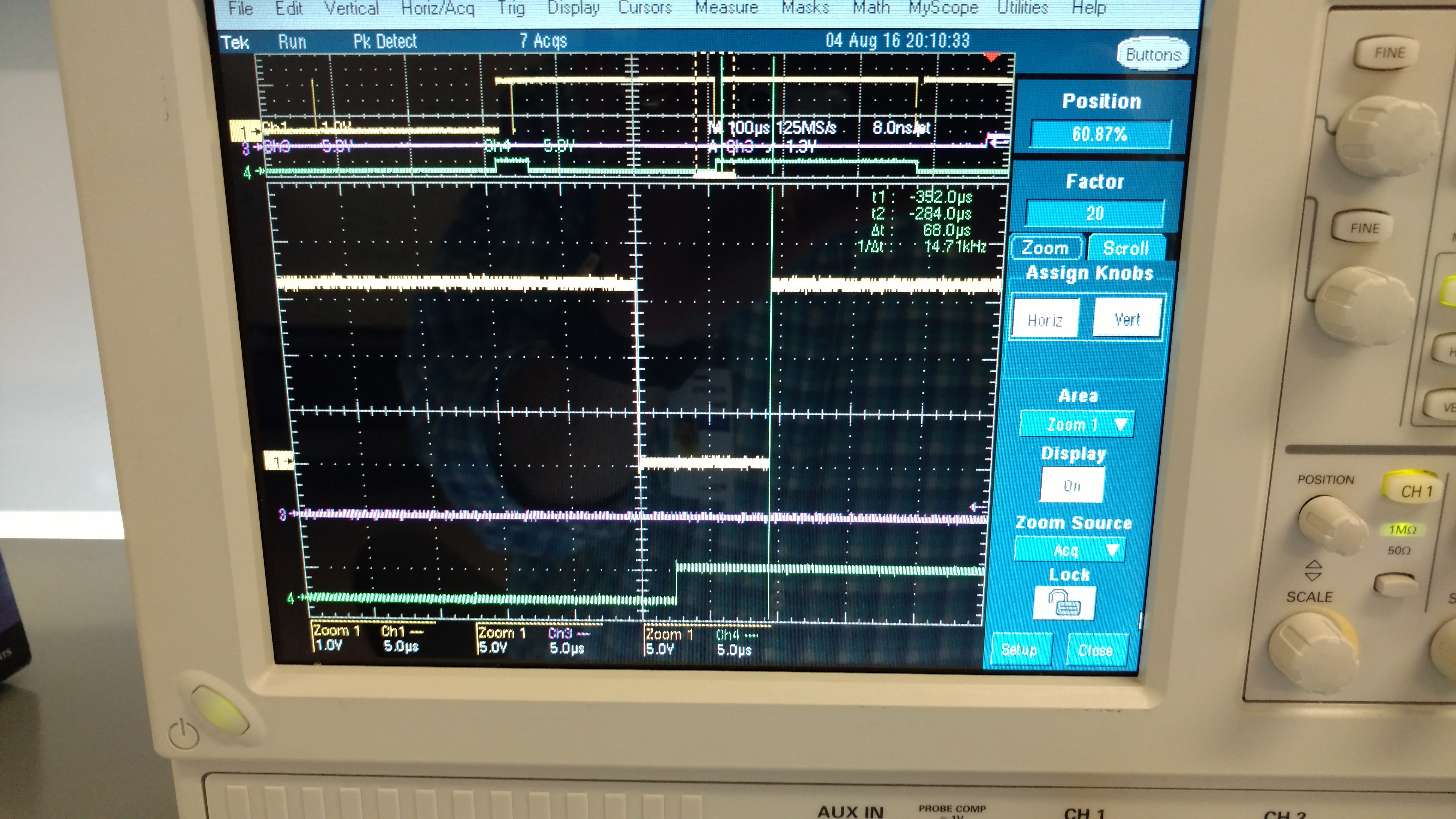
Sporadic DRDY Pulse: In the zoomed out portion you can see that the green waveform toggles twice within the 266.67 us period.

Also I noticed that the DRDY was inverted for some time at power up - it was low and would pulse high for 10 us after every 266.67 us. You can see this in the first screenshot above (Good DRDY Pulse. It is the top zoomed out portion. After some time it seemed to fix itself. Any idea why it would be doing this?

Pinakin 


  • Hello Pinakin,

    There are two things going on here:

    1. When you are not sending SCLK signals to the ADS1278, /DRDY is expected to idle low since the data is not being read. You will see /DRDY return high just before the next falling edge, indicating that a new sample is ready. This is described in Figure 76 on page 30 of the datasheet.
    2. If you are reading the data and sending SCLK, /DRDY will return high in sync with the first falling edge of SCLK. The pulse width of /DRDY will depend on how long of a delay there is between the /DRDY falling edge and the first SCLK falling edge.

    Lastly, make sure that you are following all SPI Format timing requirements on page 8. These are important to ensure that the data output is not corrupted and that your DSP does not miss any new data. If you would like any help with that, please attach another scope image that shows CLK, /DRDY and SCLK together.

    Best Regards,

  • Ryan,

    I do a sync pulse only at powerup. There after I do not sync. The sporadic DRDY pulse shows up after that point.

    When DRDY interrupt is triggered I set up DMA in the ISR which handles the clock and data fetching over SPI. I see a bad DRDY pulse when I am out of ISR and DMA is in middle of fetching data. I do see the clock and data on digital bus decoder. The bad DRDY pulse is caught on analog channel (the screenshots I sent you previously).

    Here are the screenshots of ADC SPI capture on digital bus decoder. This one cannot catch the DRDY sporadic pulse. Refer to the previous message I sent if you need that. The 3 screenshots below are showing DRDY for good scenario. There are 2 ADC chips with total 16 channels. So I am fetching 48 bytes everytime DRDY is pulsed low.

    1. Zoomed out:

    2. Zoomed in to show the beginning of data bytes being fetched on SPI by DMA:

    3. Zoomed in to show clock for each byte fetch:

    Pinakin


  • Hi Pinakin,

    My point remains the same. After you synchronize your two ADS1278 devices, the ADCs will be converting simultaneously and each device will output a /DRDY signal. If you are not reading the data, /DRDY will idle low and return high for the minimum pulse width duration before it goes low again, indicating that there is new data.

    If you are reading the data and sending SCLK, /DRDY will return high on the first SCLK falling edge. If your DMA is still fetching the 48 bytes of data before the next /DRDY pulse arrives, you will lose the LSBS of the old data and begin reading the MSBs of the new data.

    In your analog scope images, it looks like the test pin voltage never goes high because the /DRDY pulse duration is too short for your routine to notice it. If you were to recapture this image with /DRDY and SCLK together, you will see why /DRDY is going high so quickly.

    Best Regards,

  • Ryan,

    I will provide you screenshots with clock soon.

    I know the reason why DRDY goes high (which is the first falling edge of SCLK like you said). I am NOT asking why the DRDY pulse is so short. The question I am asking is that ADC is supposed to pulse DRDY line low after every 266.67 us (for 9.6 MHz low speed mode). I see this happening on scope but once in a while I see that it does it must sooner than that and that is when I have a problem reading bytes from ADC. This is when my DMA has already initiated SPI read and it get reconfigured.

    Pinakin