Hello,
I've been reading different post in here but non of it represents my problem.
I made a prototype using ADS1298 and a NXP1769 MCU, decided to use bipolar in the design but until yesterday I used unipolar power supply with no problem at all for reading the ID and write in the GPIO registers of the ADS so I thought that is was working fine. Today I connected the bipolar power supply and its not working at all. I double check the voltages of:
AVDD: 1.5V
AVSS: - 1.5V
DVDD: 3.3 V
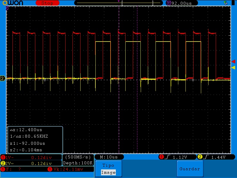
Using this bipolar configuration and the same code I'm not able to read ID register or use the GPIO, BUT rarely when the code start for asking samples of the testing signal (the same code used to get ID, GPIO and the testsignal) Ive got a 16KHz DATAREADY, but I dont know what this means because the code is made for a 500SPS sampling.
I use the internal oscillator, which I understand is 2.048MHz, by connecting the pin CLKSEL (52) to DVDD, 3.3 V.
Then, i set the following sequence:
Wait for oscillator to beggin.
Get all pins to 0.
Wait for power supplies,
Set PWDN to 1.
Send Command RESET 0x06
Ive also test that the Voltage between VCAP1's terminals reachs 1.1V before sending any other command command.
Then send SDATAC, and write configuration registers as:
CONFIG3 0xC0
CONFIG1 0xC6
CONFIG2 0x10
After this, if only connect the positive power source, im able to read ID correctly and use the GPIOs. But with the bipolar configuration that do nothing (read 0x00) and GPIOS do not activate.
If code nedeed, I attached it in this post. I use several functions CMSIS so if you have any idea whats going on I can debug it and reply.
/*
===============================================================================
 Name        : main.c
 Author      :
 Version     :
 Copyright   : Copyright (C)
 Description : main definition
===============================================================================
*/

#ifdef __USE_CMSIS
	#include "LPC17xx.h"
#endif

#include <cr_section_macros.h>
#include <NXP/crp.h>

// Variable to store CRP value in. Will be placed automatically
// by the linker when "Enable Code Read Protect" selected.
// See crp.h header for more information
__CRP const unsigned int CRP_WORD = CRP_NO_CRP ;

/*include files here*/
#include <lpc17xx_pinsel.h>
#include <lpc17xx_gpio.h>
#include <lpc17xx_systick.h>
#include <debug_frmwrk.h>
#include <lpc17xx_gpio.h>
#include <lpc17xx_spi.h>
#include <lpc17xx_exti.h>

/*insert definitions*/
void SysTick_Handler (void);
void Delay(void);
void SetSPI(void);
void Init_ADS1298(void);
void Init_Systick(void);
void SlaveSelectInit(void);
void SendCommand(uint8_t);
void WriteReg(uint8_t, uint8_t);
void ReadReg(uint8_t);
void Reset_ADS1298(void);
void Led_On(void);
void Led_Off(void);
void CS_Force(int32_t);
void EINT0_init(void);
void EINT0_IRQHandler(void);


/*insert defines here*/
#define CMD_SIZE 		1
#define CMD_SIZE_RX		2
#define Ts		500
#define Seg		1


/* CommandsADS1298 */
#define ADS_RESET 	0x06
#define CONFIG1_VAL 0xC6 //06
#define CONFIG2_VAL 0x10
#define CONFIG3_VAL 0xC0
#define TEST_SIGNAL_ON 0x35
#define SDATAC		0x11
#define RDATAC		0x10
#define CHANNEL_OFF 0x81

/* Config Registers */
#define CH1SET 	0x05
#define CH2SET 	0x06
#define CH3SET 	0x07
#define CH4SET 	0x08
#define CH5SET 	0x09
#define CH6SET 	0x0A
#define CH7SET 	0x0B
#define CH8SET 	0x0C
#define CONFIG1 0x01
#define CONFIG2 0x02
#define CONFIG3 0x03
#define ID_REG	0x00
#define GPIO	0x14
#define LED1	0xF0


/*Power and Reset*/
#define	START_PORT		0
#define	START_PIN		0
#define PWDN_PORT		0
#define	PWDN_PIN		23

/*SPI*/
#define	SPI_PORT_NUM	0
#define	SPI_PIN_SCK		15
#define SPI_FUNC_SCK	3
#define	SPI_PIN_SSEL	16
#define	SPI_PIN_MISO	17
#define	SPI_PIN_MOSI	18
#define	SPI_SSEL_ENABLE		1
#define	SPI_SSEL_DISABLE	0
#define SPI_DATABIT_SIZE 8

/*General Pins*/
#define PIN_OPENDRAIN	0
#define PIN_OUTPUT 		1
#define PIN_INPUT		0

/*insert global variables here*/
volatile uint8_t block_Time_ms = 0;
uint8_t Tx_Buf[CMD_SIZE];
uint8_t Rx_Buf[CMD_SIZE_RX];
SPI_DATA_SETUP_Type xferConfig;
int index = 0;
int ECG_input[Ts*Seg] = {0};

int main (void){

	/* Routine for systick */
	Init_Systick();

	/* Routine for initialization of the ADS1298 described in its Datasheet*/
	Init_ADS1298();
	SetSPI();

	/*Slave select*/
	SlaveSelectInit();
	Reset_ADS1298();

	/*SendCommand*/
	CS_Force(SPI_SSEL_DISABLE);
	block_Time_ms = 5;		/* wait for 1000 msg */
	while(block_Time_ms); 	/* blocking for time */
	SendCommand((uint8_t)SDATAC); /* Stop Read Data Continuously mode */
	block_Time_ms = 5;		/* wait for 1000 msg */
	while(block_Time_ms); 	/* blocking for time */
	CS_Force(SPI_SSEL_ENABLE);

	/* Routine for initialization of External Interrupt 0 */
	EINT0_init();

	/*WriteToRegister - Escribir aca*/
	/*Configuration*/
	WriteReg((uint8_t)CONFIG3,(uint8_t)CONFIG3_VAL); /*  */
	WriteReg((uint8_t)CONFIG1,(uint8_t)CONFIG1_VAL); /*  */
	WriteReg((uint8_t)CONFIG2,(uint8_t)CONFIG2_VAL); /* Configure CONFIG2 with values for TestSignal */

	/*ReadIDRegister*/
	ReadReg((uint8_t)ID_REG);
	WriteReg((uint8_t)GPIO,(uint8_t)LED1); /* */

	SendCommand((uint8_t)SDATAC); /* Stop Read Data Continuously mode */
	WriteReg((uint8_t)CONFIG1,(uint8_t)0xC6); /*  */

	/*Test Signal*/
	/* Turn On only CH1 - others are OFF */
	WriteReg((uint8_t)CH1SET,(uint8_t)TEST_SIGNAL_ON);
	WriteReg((uint8_t)CH2SET,(uint8_t)CHANNEL_OFF);
	WriteReg((uint8_t)CH3SET,(uint8_t)CHANNEL_OFF);
	WriteReg((uint8_t)CH4SET,(uint8_t)CHANNEL_OFF);
	WriteReg((uint8_t)CH5SET,(uint8_t)CHANNEL_OFF);
	WriteReg((uint8_t)CH6SET,(uint8_t)CHANNEL_OFF);
	WriteReg((uint8_t)CH7SET,(uint8_t)CHANNEL_OFF);
	WriteReg((uint8_t)CH8SET,(uint8_t)CHANNEL_OFF);
	/* Start Read Data Continuously mode */
	SendCommand((uint8_t)RDATAC);

	/*Turn on START pin - Active High*/
	GPIO_SetDir(START_PORT, (1<<START_PIN), PIN_OUTPUT);
	GPIO_ClearValue(START_PORT, (1<<START_PIN));
	GPIO_SetDir(START_PORT, (1<<START_PIN), PIN_OUTPUT);
	GPIO_SetValue(START_PORT, (1<<START_PIN));

	/*Wait for the 500 samples*/
	while(index<Ts*Seg);
	SendCommand((uint8_t)SDATAC); /* Stop Read Data Continuously mode */
	while(1);
	return 0;

}

void Init_Systick(void){
	SYSTICK_InternalInit(100); //100msg=0.1sg
	SYSTICK_IntCmd(ENABLE);
	SYSTICK_Cmd(ENABLE);
}

void SetSPI(void){

	PINSEL_CFG_Type PinCfg;
	SPI_CFG_Type SPI_ConfigStruct;

	/* * Initialize SPI pin connect
	* P0.15 - SCK;
	* P0.16 - SSEL - used as GPIO
	* P0.17 - MISO
	* P0.18 - MOSI */

	PinCfg.Portnum = SPI_PORT_NUM;
	PinCfg.Pinnum = SPI_PIN_SCK;
	PinCfg.Funcnum = PINSEL_FUNC_3;		/* P0[15] = 0/ TXD1 = 1/ SCK0 =2 / SCK = 3 */
	PinCfg.OpenDrain = PINSEL_PINMODE_NORMAL;
	PinCfg.Pinmode = PINSEL_PINMODE_PULLUP;
	PINSEL_ConfigPin(&PinCfg);

	PinCfg.Pinnum = SPI_PIN_SSEL;		/* P0[16] = 0 / RXD1 = 1 / SSEL0 = 2 / SSEL = 3 */
	PinCfg.Funcnum = PINSEL_FUNC_0;
	PINSEL_ConfigPin(&PinCfg);

	PinCfg.Pinnum = SPI_PIN_MISO;		/* P0[17] = 0 / CTS1 = 1 / MISO0 = 2 / MISO = 3 */
	PinCfg.Funcnum = PINSEL_FUNC_3;
	PINSEL_ConfigPin(&PinCfg);

	PinCfg.Pinnum = SPI_PIN_MOSI;		/* P0[18] = 0 / DCD1 = 1 / MOSI0 = 2 / MOSI = 3 */
	PINSEL_ConfigPin(&PinCfg);

	/*IMO, is CPH = 1, CPOL = 0*/
	SPI_ConfigStruct.CPHA = SPI_CPHA_SECOND;/* SPI_CPHA_FIRST: first clock edge / SPI_CPHA_SECOND: second clock edge */
	SPI_ConfigStruct.CPOL = SPI_CPOL_HI; /* SPI_CPOL_HI: high level SPI_CPOL_LO: low level */
	SPI_ConfigStruct.ClockRate = 2000000;
	SPI_ConfigStruct.DataOrder = SPI_DATA_MSB_FIRST; /* Data order, should be: SPI_DATA_MSB_FIRST: MSB first / SPI_DATA_LSB_FIRST: LSB first */
	SPI_ConfigStruct.Databit = SPI_DATABIT_SIZE; /* Databit number, should be SPI_DATABIT_x, where x is in range from 8 - 16 */
	SPI_ConfigStruct.Mode = SPI_MASTER_MODE; /*SPI_MASTER_MODE: Master mode / SPI_SLAVE_MODE: Slave mode*/

	/* Initialize SPI peripheral with parameter given in structure above */
	SPI_Init(LPC_SPI, &SPI_ConfigStruct);
}

void Init_ADS1298(void){

	/* From ADS1298 Datasheet - Power-Up Sequencing - ADS1298 - Front End Biometrico.pdf - page: 42*/
	/* Wait for Oscillator to start */
	block_Time_ms = 100;		/* wait for 500 msg > 128 msg */
	while(block_Time_ms); 	/* blocking for time */

	/* 1 - Before device power-up, all digital and analog inputs must be low. */
	/* The SPI protocol has 4 pines and only 3 of them are inputs for the ADS */

	/* Turn off SPI_PIN_SCK */
	GPIO_SetDir(SPI_PORT_NUM, (1<<SPI_PIN_SCK), PIN_OUTPUT);
	GPIO_ClearValue(SPI_PORT_NUM, (1<<SPI_PIN_SCK));

	/* Turn off SPI_PIN_MOSI */
	GPIO_SetDir(SPI_PORT_NUM, (1<<SPI_PIN_MOSI), PIN_OUTPUT);
	GPIO_ClearValue(SPI_PORT_NUM, (1<<SPI_PIN_MOSI));

	/* Turn off SPI_PIN_SSEL */
	GPIO_SetDir(SPI_PORT_NUM, (1<<SPI_PIN_SSEL), PIN_OUTPUT);
	GPIO_ClearValue(SPI_PORT_NUM, (1<<SPI_PIN_SSEL));

	/*2 - Also, in this ECG project, we use START and /PDWN (power down; active low)*/
	GPIO_SetDir(START_PORT, (1<<START_PIN), PIN_OUTPUT);
	GPIO_ClearValue(START_PORT, (1<<START_PIN));

	GPIO_SetDir(PWDN_PORT, (1<<PWDN_PIN), PIN_OUTPUT);
	GPIO_ClearValue(PWDN_PORT, (1<<PWDN_PIN));

	/* Wait for 2^18*tclk = 2^18*(488ns) = 0.128 sg waiting until power supply stabilized */
	block_Time_ms = 100;		/* wait for 500 msg > 128 msg */
	while(block_Time_ms); 	/* blocking for time */

	/* Now, disable PWDN (power down), remember that is low active, so must be in 1*/
	GPIO_SetValue(PWDN_PORT, (1<<PWDN_PIN));
	block_Time_ms = 100;		/* wait for 1000 msg */
	while(block_Time_ms); 	/* blocking for time */

}

void SysTick_Handler (void){
	if (block_Time_ms)
		block_Time_ms -- ;
}

void SlaveSelectInit(void){
	/* Turn off SPI_PIN_SSEL */
	GPIO_SetDir(SPI_PORT_NUM, (1<<SPI_PIN_SSEL), PIN_OUTPUT);
	GPIO_SetValue(SPI_PORT_NUM, (1<<SPI_PIN_SSEL));
}

void CS_Force(int32_t state)
{
	if (state){
		GPIO_SetValue(SPI_PORT_NUM, (1<<SPI_PIN_SSEL));
	}else{
		GPIO_ClearValue(SPI_PORT_NUM, (1<<SPI_PIN_SSEL));
	}
}

void SendCommand(uint8_t command1){

	Tx_Buf[0] = command1;

	xferConfig.tx_data = Tx_Buf;		/* Pointer to transmit data */
	xferConfig.rx_data = Rx_Buf;		/* Pointer to receive data */
	xferConfig.length = sizeof(uint8_t);	/* Length of transfer data */
	block_Time_ms = 2;		/* wait for 1000 msg */
	while(block_Time_ms); 	/* blocking for time */
	SPI_ReadWrite(LPC_SPI, &xferConfig, SPI_TRANSFER_POLLING);

}

void WriteReg(uint8_t command,uint8_t value){

	/* From 1298 Datasheet - WREG - p.41*/
	/* This OPCOD writes registers data. Its a two bytes opcode + 1 byte input
	 * First opcode: 010r rrr ... where xxxr rrrr is the starting register address. so make a mask OR with |0x40
	 * Second opcode: 000n nnnn ... where xxxn nnnn is the number of registers to write -1
	 * After opcodes, registers data follows (in MSB if more than 1). */

	/*For this implementation will write only one register at time. So, secondopcode is 0 (1-1)*/
	CS_Force(SPI_SSEL_DISABLE);
	block_Time_ms = 5;		/* wait for 1000 msg */
	while(block_Time_ms); 	/* blocking for time */
	SendCommand(command|0x40);
	SendCommand(0x00);
	SendCommand(value);
	block_Time_ms = 5;		/* wait for 1000 msg */
	while(block_Time_ms); 	/* blocking for time */
	CS_Force(SPI_SSEL_ENABLE);
}

void ReadReg(uint8_t command){

	/* From 1298 Datasheet - RREG - p.41*/
	/* This OPCOD writes registers data. Its a two bytes opcode + 1 byte input
	 * First opcode: 010r rrr ... where xxxr rrrr is the starting register address. so make a mask OR with |0x40
	 * Second opcode: 000n nnnn ... where xxxn nnnn is the number of registers to write -1
	 * After opcodes, registers data follows (in MSB if more than 1). */

	/*For this implementation will write only one register at time. So, secondopcode is 0 (1-1)*/
	CS_Force(SPI_SSEL_DISABLE);
	block_Time_ms = 5;		/* wait for 1000 msg */
	while(block_Time_ms); 	/* blocking for time */
	SendCommand(command|0x20); /* Opcode */
	SendCommand(0x00); /* length */
	SendCommand(0x00); /* Dummy for response */
	block_Time_ms = 5;		/* wait for 1000 msg */
	while(block_Time_ms); 	/* blocking for time */
	CS_Force(SPI_SSEL_ENABLE);
}

void Reset_ADS1298(void){
	/* Transmit a reset pulse */
		/* Reset pulse is always off by hardware */
		/* Send RESET command */
		block_Time_ms = 50;		/* wait for 1000 msg */
		while(block_Time_ms); 	/* blocking for time */
		CS_Force(SPI_SSEL_DISABLE);
		block_Time_ms = 20;		/* wait for 1000 msg */
		while(block_Time_ms); 	/* blocking for time */
		SendCommand((uint8_t)ADS_RESET);
		block_Time_ms = 30;		/* wait for 1000 msg */
		while(block_Time_ms); 	/* blocking for time */
		CS_Force(SPI_SSEL_ENABLE);
		block_Time_ms = 50;		/* wait for 1000 msg */
		while(block_Time_ms); 	/* blocking for time */
}

void Led_On(void){
	GPIO_SetDir(0, 1<<20, 1);
	GPIO_SetValue(0,1<<20);
}

void Led_Off(void){
	GPIO_SetDir(0, 1<<20, 1);
	GPIO_ClearValue(0,1<<20);
}


void EINT0_init (void){

	PINSEL_CFG_Type pin_config;
	EXTI_InitTypeDef EINT0_config;

	/* Configure pin */
	pin_config.Portnum=2;
	pin_config.Pinnum=10;
	pin_config.Funcnum=0x1;
	pin_config.Pinmode=PINSEL_PINMODE_PULLUP;
	pin_config.OpenDrain=PINSEL_PINMODE_NORMAL;
	PINSEL_ConfigPin (&pin_config);

	/* Configure EINT0 */
	EINT0_config.EXTI_Line=EXTI_EINT0;
	EINT0_config.EXTI_Mode=EXTI_MODE_EDGE_SENSITIVE;
	EINT0_config.EXTI_polarity=EXTI_POLARITY_LOW_ACTIVE_OR_FALLING_EDGE;
	EXTI_Config(&EINT0_config);

	/* Clear existing flag */
	EXTI_ClearEXTIFlag(EXTI_EINT0);

	/* Enable EINT0 */
	NVIC_EnableIRQ(EINT0_IRQn);

}

void EINT0_IRQHandler() {

	unsigned char CANAL[27];

	/* Clear existing flag */
	EXTI_ClearEXTIFlag(EXTI_EINT0);

	xferConfig.tx_data = (void *) NULL;		/* Don't need transmit data */
	xferConfig.rx_data = (void *) CANAL;	/* Pointer to receive data */
	xferConfig.length = 27-1;	/* Just read */
	SPI_ReadWrite(LPC_SPI, &xferConfig, SPI_TRANSFER_POLLING);

	ECG_input[index] |= ( CANAL[3] << 16 );
	ECG_input[index] |= ( CANAL[4] <<  8 );
	ECG_input[index] |= ( CANAL[5]       );

	/*And for the MSB of the integer, must conserve the sign bit of two-complement*/
	if( CANAL[3] & 0x80 ){
		ECG_input[index] |= (0xFF) << 24;
	}else{
		ECG_input[index] |= (0x00) << 24;
	}

	index++;
}