This thread has been locked.

If you have a related question, please click the "Ask a related question" button in the top right corner. The newly created question will be automatically linked to this question.

Issue with interfacing to ADS1292R(ID Read)

Other Parts Discussed in Thread: ADS1292R, ADS1292

Dear Team,

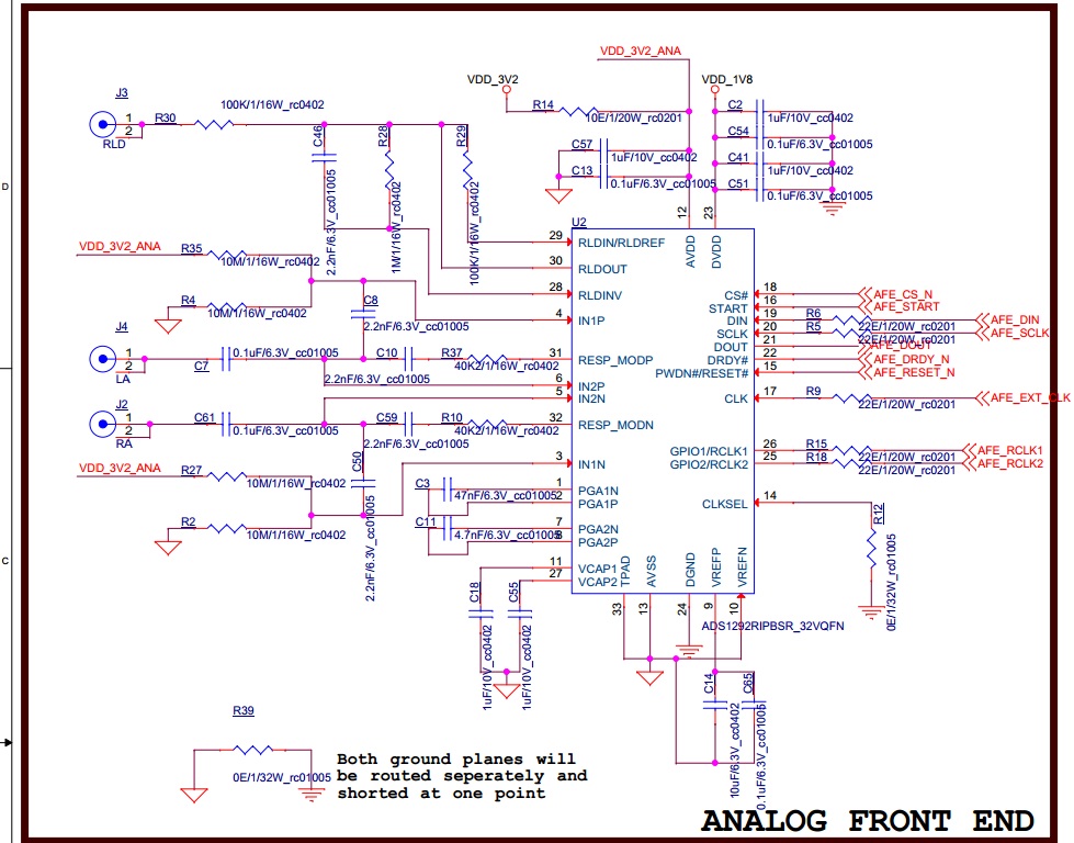
We have interfaced ADS1292R to our MCU(Cortex M4 based) in our custom application board.

We tried to read the Device ID over SPI, but seems to have no success after trying out many experiments.

Below is the configuration/sequence of operation for the "Read ID":

=> MISO, MOSI, SCLK, NPCS pins are configured for SPI mode

=> START pin configured as Output.

=> RESET pin configured as Output and HIGH.

=> DRDY pin configured as input with Pull-up.

=>  AFE is configured for and fed with External Clock of 512kHz (CLKSEL tied to GND).

=> SPI Initialised with Frequency of 1MHZ, CPOL to be 0 and CPHA to be 1, 8-bit transfer mode, CS stay LOW for complete transfer etc.

=> Generated a RESET sequence on the RESET PIN with a LOW pulse, and then made it to be HIGH.

=> Issued a STOP command (0x0A) as well as SDATAC(0x11) to the ADS1292R device.

=> Issued a RREG (0x20, 0x00 ) command to read 1 byte(with a Dummy byte write) of Device ID.

 => But, the read data never comes 0x73 (as per datasheet for ADS1292R). We seem to be still receiving the sample data from conversion.

We tried analysing the data received, and the data sequence is as: 0xC0, 0x60, 0x00, 0x7F, 0xFF, 0xFF....

Kindly suggest us, what  sequence of initialisation/configuration to be followed to read the device ID from ADS1292R.

Thanks,

Umakanta Patro

  • Umakanta,

    I'm moving your post to the correct forum.

  • Hi Umakanta,

    By your description above, it sounds like you are doing the correct sequence to read the ID register of the ADS1292. Can you please post a screen capture of your SPI communication lines and possible a schematic of the area around the ADS1292?
  • HI,

    Sorry for the late response.

    I couldn't capture the SPI transaction waveform. But, what I feel is, if i wasn't doing correct sequencing for SPI, then I wouldn't have correctly receiving those data of 9 bytes(3 bytes Header+6 Bytes sampled data).

    Now, we tried doing the following sequence to to stop the continuous data streaming mode and to get the device to respond to  other command, but still the device seems to be sending out data for each write(each clock, irrespective of the data we write):

    -> Perform a RESET and Pull RESET line HIGH.

    -> Configure the START pin LOW for a delay and make it HIGH.

    -> Check DRDY pin status, and we found it to be LOW. Which says data is available.

    -> Read 9 bytes of data (and it is valid).

    -> Configure the START pin LOW.

    -> Send Start command.

    -> Send Stop command.

    -> Check DRDY pin status, and we found it to be HIGH, Which says data is not available.

    -> Read some register data but still we receive the same sample data.

    Kindly let us know, what sequencing to be done to stop the continuous mode and put device to respond to read register or set register commands.

    Thanks,

    Umakanta 

  • Hi Umakanta,

    Please review Table 13 in the ADS1292 datasheet.  Under the Data Read Commands section you'll find RDATAC, SDATAC and RDATA.  Note that RDATAC is the default state at power up and that footnote (1) tells you that the RREG command; which is the one you need to use to read back the register content; is ignored while the device is in RDATAC mode.  After powering up the ADS1292, perform a reset, and then issue the SDATAC command.  From there, use the RREG command to view the register contents that you want to see.

  • Hi Tom,

    Thanks for the reply.

    As you see, we have done the same(all) sequencing as suggested by you, but don't know why isn't it working.
    Can you please suggest us more clues?

    Also, we observed that the MOSI(DIN) and MISO(DOUT) are staying LOW during IDLE on a reference evaluation board(with ADS1292R) whereas on our board both the lines stay HIGH during idle. We don't have any control on the Bus lines as they are driven by host controller module.
    So, will this make any difference?

    Any more inputs will be appreciated towards solving this.

    Thanks,
    Umakanta Patro

  • Hi Umakanta,

    Schematics and screen captures of your SPI interface will help us help you more. Can you verify if the data that you are recieving is actually correct based on some fixed input voltage to the ADS1292?
  • Hi Tom,

    Please find attached the schematics of AFE module.

    Please note that we are providing 1.8V to DVDD of ADS1292R. We think it is fine as the device datasheet says the range for DVDD is 1.8V-3.6V.

    Kindly review the schematics and let us know your feedback on it.

    Also, can you please throw some light towards the question about default/idle state of  MOSI(DIN) and MISO(DOUT) pins?

    Also today we tried driving the ADS1292R with internal clock(default design to drive from external clock) as well, but the result seems to be the same(no response to our commands).

    Thanks,

    Umakanta Patro

  • Hi Umakanta,

    I don't see anything obvious in your schematic that would be causing these problems you are having with the ADS1292. The MOSI and MISO being 'high' while inactive may be related to how your processor is configured (internal pull-ups active?), but in general that should not cause a problem. What would it take for you to send us a screen shot of an actual SPI write or read transaction to the device? Have you more than one board at your disposal? If so, do you see the same behavior with multiple boards?