This thread has been locked.

If you have a related question, please click the "Ask a related question" button in the top right corner. The newly created question will be automatically linked to this question.

Compatible Analog to digital converter EVM with OMAP L138 LCDK?

Other Parts Discussed in Thread: ADS1602, TLV320AIC3106, ADS8881

Dear Friends,

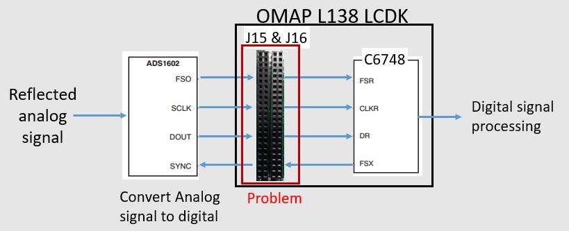
I would like to know which TI Analog to digital converter EVM is compatible with OMAP L138 LCDK. We are currently trying to interface between ADS1602 EVM and OMAP L138 LCDK, however, the job seems extremely difficult due to compatibility issues. 

Do you have any suggestions regarding a similar product to ADS1602 EVM which is also compatible with OMAP L138 LCDK?

  • Hi Sajad,

    I don't know of any 'off the shelf' evaluation boards that are directly compatible with the OMAP L138 LCDK kit.  The ADS1602 has a serial interface which is compatible with the multi-channel buffered serial port (McBSP) found on that processor.  The two McBSP ports are being used on the L138 by U23 (an eithernet tranciever device) and U22 (an audio codec TLV320AIC3106).  If you are not using the codec in your project, you can tap into the McBSP1 port there.

    As far as other suggestions on parts, what specifically are you looking to do with the ADS1602?  If you can provide some detail about your project, I might be able to suggest an alternate part for you to try. 

  • Dear Tom,

    Thank you for your reply.

    We are developing a fishfinder (sonar system).  As shown in Fig. 1, first a signal is transmitted to the ocean.

    Figure 1

    Second, the reflected signal (after hitting an object such as a fish) is received by our transducer. The received signal is analog, hence, using ADS1602, this analog signal is converted to a digital signal (Fig. 2).

    Figure 2

    If you could only answer Question 0, you could just ignore the rest of questions.

    Question 0: We have 4 output pins from our ADS1602, namely FSO, SCLK, DOUT, and SYNC. These four pins should be connected to which J15 or J16 extension pins?

    Question 1: How to properly connect the ADS1602 to the OMAP L138 LCDK? As you mention and also according to Page 10 of OMAP L138 LC Dev Kit, we could use SPI1_SCSn_6 and SPI1_SCSn_7 which are J15.15 and J15.13, respectively. 

    Question 2: Do we need to use both ports of McBSP? If yes, as you said, we need to also use the SPI connected to U23 (an eithernet tranciever device). I have already checked the OMAP L138 LC Dev Kit. According to OMAP L138 LC Dev Kit page 11, several SPIs, such as SPI0_SCSn_0 up to SPI0_SCSn_0 to SPI0_SCSn_5 as well as SPI0_CLK, SPI0_SOMI are connected to U23. Which one of these should we use?

    Note: We are already using SPIO_CLK (J15.25) as our ehrPWM output. So, perhaps we cannot use SPIO, right? 

  • Hi Sajad,

    For Q0 - there are three outputs (FSO, SCLK and DOUT) and one input (SYNC) to contend with.  Unfortunately there is nothing I see on J15 or J16 to connect them to.  The expansion headers do accomodate some SPI signals, but the ADS1602 does not have an SPI compatible interface.

    For Q1 - SPI_SCSn_6 and SPI_SCSn_7 are configured for I2C, so that won't work either.

    For Q2 - you only need one McBSP option - either McBSP0 or McBSP1.  McBSP1 seems like it has something to do with the boards 'boot options' (see SW1) so you might need to use McBSP0.

    If you can live with 1MSPS, the ADS8881 is an 18-bit SAR converter with an SPI interface that could potentially be wired into the expansion headers.

  • Dear Tom,
    You said that "the ADS1602 does not have an SPI compatible interface." Please help me better understand. The ADS1602 manual says:
    Page 22 of [http://www.ti.com/lit/ds/symlink/ads1602.pdf] says:
    "Interfacing the ADS1602 to the TMS320 DSP family: Since the ADS1602 communicates with the host via a serial interface, the most suitable method to connect to any of the TMS320 DSPs is via the multi-channel buffered serial port (McBSP). A typical connection to the TMS320 DSP is shown in Figure 54."
    Page 1 of [http://www.ti.com/lit/ds/symlink/ads1602.pdf] says that the ADS1602 has 3-Wire Serial Interface.

    I thought that the ADS1602 is SPI compatible because it uses 3-Wire Serial Interface. Then we should be able to connect our ADS1602 to any TMS320 DSP family. However, you said "the ADS1602 does not have an SPI compatible interface".

    My question: Please help me better understand what you meant by saying "the ADS1602 does not have an SPI compatible interface."
    Thank you Tom :)
  • Hi Sajad,

    A Serial Peripheral Interface (SPI) uses a burst mode clock.  There is an SPI master that sends a fixed number of clock cycles to receive a defined number of data bits from the slave device (usually 8/16/24 bits, etc).  There is a chip select, data to and from the master (MISO and MOSI) and the serial clock, which is only active while data is being transferred between the master and slave devices.

    The Multi Channel Buffered Serial Port (McBSP) is a little different, it has a defined 'frame sync' signal and the serial clock is continuous.  The data word is defined (8/12/16/24/32 bits, etc) but the start of the received word is dependent on the frame synchronization.   The McBSP can emulate an SPI interface, but most SPI interfaces can't work with the Frame Sync and a continuous clock.  A complete McBSP interface has both receive and transmit clock, frame sync and data but the receiver and transmitter can run independently.  In the case of the ADS1602, only the McBSP receiver is used along with a GPIO function to initialize the SYNC input.