


Other Parts Discussed in Thread: ADS131E08
Problem:
We are using an ADS131E08 on our board. It is observed that when the input frequency to analog input is slightly above or below 0.125fMod, the ADC exhibits Alias like behavior and there is an output amplitude of about -15dB, whereas the datasheet (figure 35) shown better than -40dB attenuation for above 55KHz.
Steps to Recreate Problem:
ADC Channel 3 used for measurement, both P and N lines biased at 1.5V DC.
Sinusoidal signal from a source is connected with AC Coupling to P input of ADC.
ADC is configured for external Clock and DR bit are set as “100”.
ADC clock is about 2.2Mhz, AVDD = 3V, AVSS=GND, DVDD=3.3V, VREFP=2.5V and VREFN = GND.
The sampling rate is 4320 Samples/Sec.
The internal gain of ADC is set as 1.
The data read from ADC by the MCU for each conversion is output on a DAC of the MCU immediately.
The DAC uses a 3.3V supply and level change when output on DAC is 3.3/5.
The input signal, DAC output and DRDY signals are observed on oscilloscope.
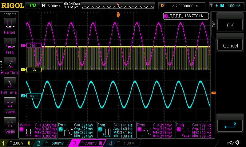
The signal amplitude from signal source is kept at 325mV rms at about 139Hz and the output of DAC is observed to make sure the test setup and gains are as expected
The signal amplitude from source is changed to frequencies near 138KHz (frequency = 0.125_MOD).
The input signal amplitude is kept at about 500mV rms.
Alias like behaviour is observed on the oscilloscope at input frequencies slightly above and below = 0.125_MOD. The waveforms are captured
First picture below is for reference when input signal is 139Hz (very low frequency compared to Sampling frequency).
The second picture below is to show the input at 139KHz. The screen is zoomed to see the High frequency and DAC output is not visible properly (see next picture)
The third picture below is to show the output of DAC. The screen is zoomed out to see the output of DAC at low frequency.

Can the experts guide us on why this is happening?
Regards,
Vinod

