This thread has been locked.

If you have a related question, please click the "Ask a related question" button in the top right corner. The newly created question will be automatically linked to this question.

ADS1247 Thermocouple temperature measurement issue.

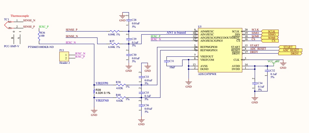
Hi, I have the following issue measuring my thermocouple output. I am able to measure temperatures above 30C with the thermocoiple shown above. When the temperature drop below 30C I am getting 7FFFFFh when reading the thermocouple output. RTD cold junction seems to work fine. I have the following settings:

Thermocouple:     static const uint8_t adc_setup_TC[] = {0x40,0x03, 0x01,0x02,0x40,0x61};

RTD:                       static const uint8_t adc_setup_RTD[] = {0x40,0x03,0x13,0x00,0x40,0x51};

Excitation:              static const uint8_t ADC_WR_SETUP_EXC[] = {0x4A,0x01,0x03,0x2F};

The excitation "ADC_WR_SETUP_EXC" is set once and never changes. I alternate between Thermocouple and RTD settings inside the  infinite loop. I read data from the thermocouple 200 ms after I apply (0x40,0x03, 0x01,0x02,0x40,0x61) thermocouple settings. I do the same for the RTD. 

spi_tx_buff_ptr = ADC_WR_SETUP_EXC; // Pointer set to ADC_WR_SETUP_EXC[] = {0x4A,0x01,0x03,0x2F}; buffer
// Reset rx buffer and transfer done flag
memset(m_rx_buf, 0, m_length_exc);
spi_xfer_done = false;
// Read internal registers into m_rx_buf
APP_ERROR_CHECK(nrf_drv_spi_transfer(&spi, (uint8_t const *)spi_tx_buff_ptr, length_read_reg, m_rx_buf, length_read_reg));
while (!spi_xfer_done)
{
__WFE();
}

for (;;){
nrf_gpio_pin_set(21); // Set Start high (START is 1)
nrf_delay_ms(1);


if ((cntr % 2) == 0){  //Every even count
      //Initialize TC ADC
     nrf_delay_ms(10);
     spi_tx_buff_ptr = adc_setup_TC;  //Initialize buffer pointer to the ADC1247 config: static uint8_t adc_setup_TC[] ={0x40,0x03,0x01,0x02,0x30,0x71};      
     memset(m_rx_buf, 0, length_rx_buf);    // Reset rx buffer and transfer done flag
     spi_xfer_done = false;
     //Configure TC ADC via SPI transfer 
     APP_ERROR_CHECK(nrf_drv_spi_transfer(&spi, (uint8_t const *)spi_tx_buff_ptr, m_length_setup_tc, m_rx_buf, m_length_setup_tc));
     while (!spi_xfer_done)
    {
        __WFE();
    }
    nrf_delay_ms(200);
   //Read Thermocouple data
   spi_tx_buff_ptr = adc_data;
   memset(m_rx_buf, 0, length_rx_buf);// Reset rx buffer and transfer done flag
   spi_xfer_done = false;
   while(nrf_gpio_pin_read (23)){} //wait for !DRDY
   //Read TC data via SPI
   APP_ERROR_CHECK(nrf_drv_spi_transfer(&spi, (uint8_t const *)spi_tx_buff_ptr, m_length_adc_data, m_rx_buf, m_length_adc_data));
   while (!spi_xfer_done)
   {
       __WFE();
   }

 TC[0] = m_rx_buf[0];
 TC[1] = m_rx_buf[1];
 TC[2] = m_rx_buf[2];
}
else{                                   //Every odd count
//Initialize RTD ADC 
nrf_delay_ms(10);
spi_tx_buff_ptr = adc_setup_RTD; //Initialize buffer pointer to the ADC config: static uint8_t adc_setup_TC[] = {0x40,0x03,0x01,0x02,0x40,0x71};
// Reset rx buffer and transfer done flag
memset(m_rx_buf, 0, length_rx_buf);
spi_xfer_done = false;
//Configure TC ADC
APP_ERROR_CHECK(nrf_drv_spi_transfer(&spi, (uint8_t const *)spi_tx_buff_ptr, m_length_setup_rtd, m_rx_buf, m_length_setup_rtd));
while (!spi_xfer_done)
{
       __WFE();
}
nrf_delay_ms(200);
//Read RTD data
spi_tx_buff_ptr = adc_data;    //Initialize buffer pointer to the ADC data read:   static const uint8_t adc_data[] = {0x00,0x00,0x00};
memset(m_rx_buf, 0, length_rx_buf);// Reset rx buffer and transfer done flag
while(nrf_gpio_pin_read (23)){} //wait for  !DRDY
APP_ERROR_CHECK(nrf_drv_spi_transfer(&spi, (uint8_t const *)spi_tx_buff_ptr, m_length_adc_data, m_rx_buf, m_length_adc_data)); // Read TC data
while (!spi_xfer_done)
{
       __WFE();
}

RTD[0] = m_rx_buf[0];
RTD[1] = m_rx_buf[1];
RTD[2] = m_rx_buf[2];

nrf_gpio_pin_clear(21); // Set Start Low (START is 0)
nrf_delay_ms(1);

// ADC is stopped
diff[0] = TC[0] + RTD[0];
diff[1] = TC[1] + RTD[1];
diff[2] = TC[2] + RTD[2];


LEDS_INVERT(BSP_LED_1_MASK);
nrf_delay_ms(200);
}

if (cntr <255)
    cntr++;
else
   cntr =0;

        }

}

Need your help, thank you.

  • Roman,


    I haven't had a chance to read through your code. However, since you're reading 7FFFFFh as data when you try to read the thermocouple, you are over ranging the inputs - the inputs are large compared to the reference.

    I can think of several things things that are possible problems that lead to this result. 1. The input is measurement is open, and AINP and AINN have drifted apart. It's also possible that you have the wrong inputs selected. 2. You have the reference setup incorrectly (wrong reference or not turned on) so that the REFP to REFN is 0 and any input is larger than that. 3. I would check to make sure the board is put together correctly. Make sure that the inputs to the ADC really does see a small thermocouple voltage and that the filter resistors are installed. Verify that you never turn off the reference.


    Joseph Wu
  • Roman,


    Checking the register settings, it looks like the device is set to keep the internal reference on for conversions and then selects REF0 for the reference. Try keeping the internal reference always on, and then selecting the internal reference as the reference (not REF0).


    Joseph Wu
  • Hi Joseph, I understand and I will verify all. The question is why the system works when temperature is above 30C?
    Thank you
  • Can you give me the actual settings?
  • Where do you see it in my configuration? This part I do not understand. How does the device switch between the internal reference and REF0?
  • Roman,


    I didn't notice that you said that the thermocouple stops working below 30C. Regardless, lets start with the thermocouple measurement setting.

    What I want to do is keep the internal reference always on because you'll need it for the RTD cold junction measurement anyway, and you'll use it for an exact measurement with the thermocouple.

    Using the MUX1 register, set the VREFCON[1:0] to 01 to always keep on the reference on. Second use REFSELT[1:0] to 10 (only when using the thermocouple) so that the internal reference is used for the ADC. You can find both bit descriptions on page 59 of the datasheet. To set up the thermocouple measurement, you will use:

    {0x40,0x03,0x01,0x02,0x30,0x61} (WREG, starting at 00h, four bytes).

    This sets the device to measure AIN0 to AIN1 (as AINP and AINN respectively), setting VBIAS to AIN1 which would be the negative input of the ADC. The next two bytes sets the internal reference as always on, and the ADC uses the internal reference. The PGA is set to 64 and the data rate is 10SPS.

    If you continue to have problems, try lowering the gain to check to see if there's a problem with the common-mode input range. However, you already have the negative input set to VBIAS which should work.


    Joseph Wu
  • Hi Joseph, I tried the settings you have recommended as well as the following:
    static const uint8_t adc_setup_TC[] = {0x40,0x03, 0x01,0x02,0x30,0x01};

    The result is always the same, the output counts down to zero and the jumps to decimal 8388445, 8388428, ....
    Which is 7FFF5D, 7FFF4C, ... weired.
    Help.
  • Roman,


    It's strange that the output starts at 0 and then jumps to near full scale. Do you do any sort of calibration? It might help to issue a SELFOCAL to null out any offset that the ADC might see.

    However this doesn't help when the input is very close to the positive full scale voltage.

    I would start measuring the voltages on the board. Check AIN1 to ground to see that the VBIAS is connected. Measure REF0P to REF0N to see that there is current going across the resistor. Measure VREFOUT to VREFCOM to make sure the internal reference is on. I'd go through the whole board to check that every voltage is correct.


    Joseph Wu