This thread has been locked.

If you have a related question, please click the "Ask a related question" button in the top right corner. The newly created question will be automatically linked to this question.

ADC12J4000 SFDR vs Decimation Factor

Other Parts Discussed in Thread: ADC12J4000

Hello Team,

We received the below questions from one of our customers on the ADC12J4000 device:

The following figure, page 18 from the datasheet represents the SFDR vs the decimation factor. It shows that when the Decimator factor increases, better is the SFDR.

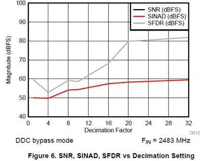
I don’t understand why the SFDR depends of Decimation factor. Could you explain me the reason of this improvement? Is it true concerning other frequency signals (between 1GHz to 2GHz at 4GSPS)?

Supposing that the decimation is realized in a FPGA (reproducing the same digital filters that the ADC), could we have the same trend? In other words, is this trend only depends on the decimation or is exists another reason?

Thank you in advance.

Kind Regards,

Mo.

  • Hi Mo

    That chart is for a specific set of conditions: Fs = 4000MSPS, Fin = 2483 MHz, Fnco set to shift the input frequency within the bandwidth of the decimation filter.

    As the decimation factor increases, the output bandwidth decreases. As this happens, more and more of the harmonic and spur products fall outside of the bandwidth of the decimation filter. This effectively increases the SFDR of the converter for that condition.

    The actual SFDR in a customer system will depend on the specific sample rate, input frequency, NCO frequency and decimation setting.

    If the mixing and decimation steps are done in an FPGA the results should be similar, however implementing the NCO, Complex Mixer and Decimation filters for an ADC sample rate of 4000 MSPS will not be trivial.

    Best regards,

    Jim B

  • Hi Jim,

    Thank you for the clarification. We will inform the customer about this.

    Kind Regards,
    Mo.