This thread has been locked.

If you have a related question, please click the "Ask a related question" button in the top right corner. The newly created question will be automatically linked to this question.

ADS5263 EVM issues

Other Parts Discussed in Thread: ADS5263

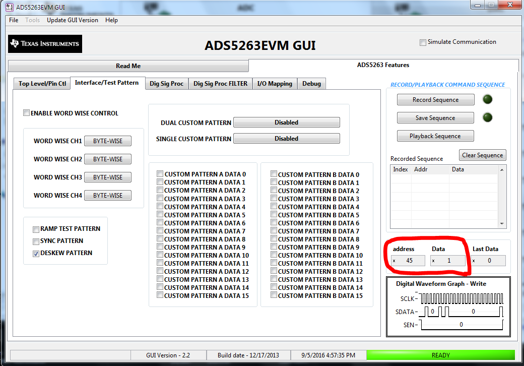
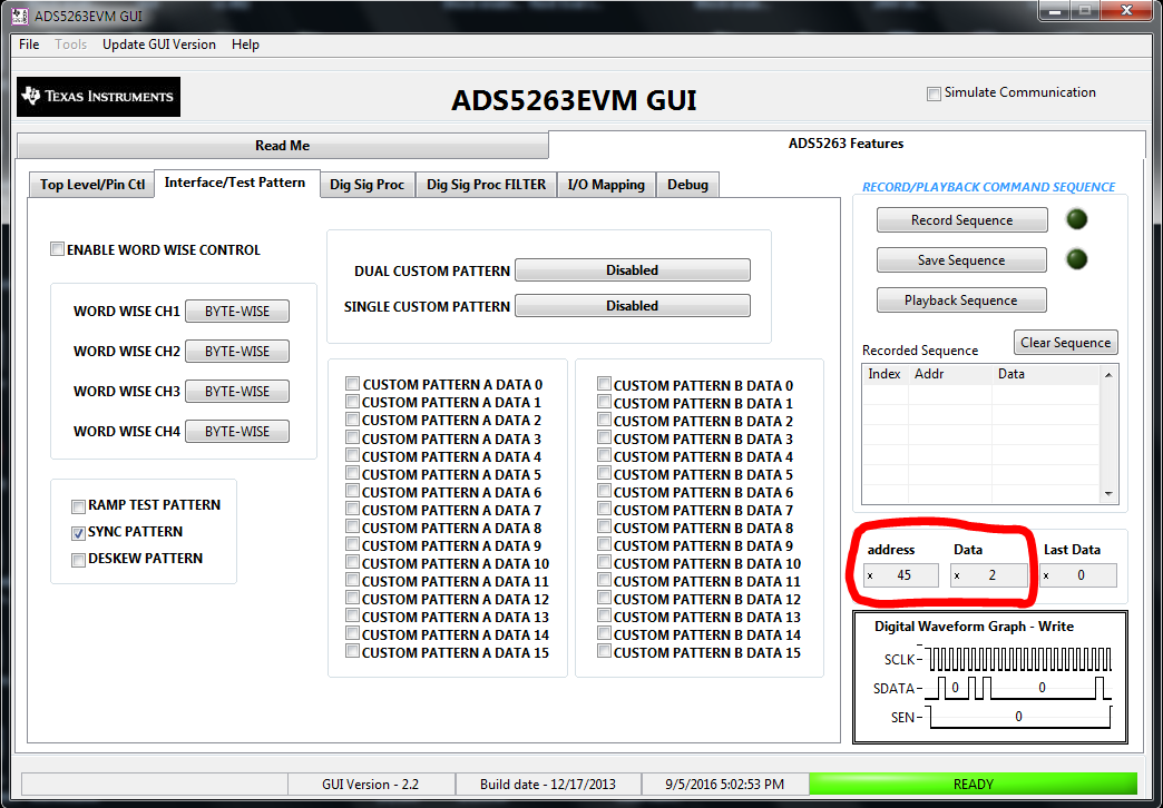
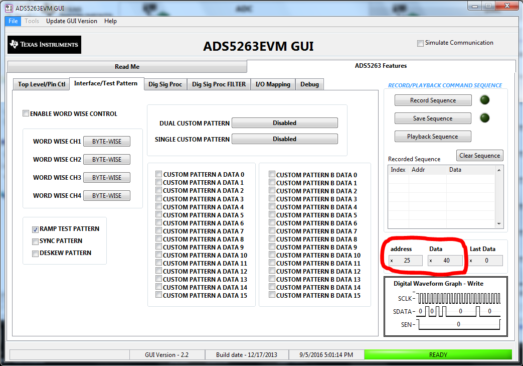
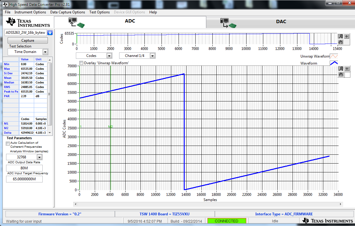
I am trying to get this dev board to work connected to a Cyclone V GT development kit. I am using the TI ADC to HSMC adapter board to connect the boards. Currently I have reduced the sampling rate to 20MHz on 1 lane in order to prevent any clocking time issues. The goal is to eventually run at the full 100MHz on 2 lanes. I have been able to get the deskew pattern of 0xAAAA to come back correctly. I have also gotten the 0xFF00 sync pattern to come correctly. I am having trouble getting the ramp correct though. Is there something I'm missing, I would of thought having these two patterns coming back correctly would be enough to get the timing correct but that doesn't seem to be the case?

  • Hello Jason,

    We have received your post regarding the ADS5263 and I have assigned it to the device application experts. They will get back to you soon with any updates on this.
  • Hi Jason,

    Thanks for using ADS5263 device.

    This device data output is using serial LVDS.

    For this detail information, please refer to www.ti.com/lit/pdf/sbaa205

    (LVDS application note).

    If you are running at 20MHz (clock) on 1 lane (1-Wire) mode, assuming you are using the following:

    If you are running at 100MHz (clock) on 2 lanes (2-Wire) mode, assuming you are using the following data type:

    Please make sure your Cyclone V GT can run BIT CLOCK (by using DDR) up to Freq=4*100=400MHz

    (i.e., 800M DDR rate).

    And the Frame Clock = 0.5 *100=50MHz

    Thanks and best regards,

    Chen

  • Hi Jason,

    For testing ADS5263 EVM by using TSW1400 EVM to capture the raw LVDS data.

    1) We measured DESKEW pattern mode by setting Addr=0x45 Data=0x0001

    1) We measured SYNC pattern mode by setting Addr=0x45 Data=0x0002

    1) We measured RAMP pattern mode by setting Addr=0x25 Data=0x0040

    Please try this way. You may capture correct output data.

    Thanks for using ADS5263 EVM.

    Best regards,

    Chen'

  • So, the problem I'm having is the ramp did not produce correct results running 20MHz on 1 wire mode. It looked like noise. This wasn't workign so I decided to go to 2-wire mode. So, I took the same component in VHDL, changed the word length from 16 to 8 bits. I then created two instances of them and concatenated them (ie. byte-wise mode). I then was able to get a correct ramp and deskew, but the sync pattern was reading 0xF0F0. However, when I applied the single custom pattern and set it to 0xFF00, it came back as 0xFF00. That being said I am using an Altera Cyclone V GT development kit instead of the TSW1400 EVM, but 20MHz should be easily doable. I also had trouble getting the double pattern to work from the menu. I set alternating patterns of 0xFFFF and 0x0000 and set the Dual Custom pattern, but I only saw 0xFFFF. I also noticed that it mentions bit-wise mode in the data sheet, but I see no register value that can produce it.

  • Your output pattern for the sync code is showing 0xF0F0, but the data sheet is saying it should be 0xFF00. From the data sheet

    D1 <SYNC PATTERN>
      0 Sync pattern disabled.
      1 Sync pattern enabled.
      All channels output a repeating pattern of 8 1s and 8 0s instead of ADC data.
      Output data
      [15...0] = 0xFF00

    Is this a typo in the data sheet?

  • Hi Jason

    Thanks for your comparison for these two.
    We will check into the captured data again.
    We will let you know soon.

    Thank you!
    Best regards,
    Chen
  • Hi Jason,

    Yes, we also followed your condition 2-wire mode and set the single CUSTOM Pattern on the register.

    as follows:

    And then we measured the signal output using TSW1400:

    The data shows 0xFF00 (same as you have seen.)

    Also, we tested 1-wire mode and set the SYNC Pattern on the register.

    as follows:

    And then we measured the signal output using TSW1400:

    The data also shows 0xFF00 (Note: this shows the output data are different between 1-wire mode and 2-wire mode).

    Thanks and best regards,

    Chen

  • Hi Jason,

    So from the data sheet, it says Output data [15..0]=0xFF00
    That could mean it is only for 1-wire mode
    but not for other modes.
    I would like to check with other engineers for this concern.

    Thanks and best regards,
    Chen
  • Hi Jason,

    Yes, from ADS5263 data sheet:

    D1 <SYNC PATTERN>

    0 Sync pattern disabled.

    1 Sync pattern enabled.


    All channels output a repeating pattern of 8 1s and 8 0s instead of ADC data.

    Output data

    [15...0] = 0xFF00

    This data sheet SYNC pattern is speced:
    [15..8]=0xFF
    [7:0]=0x00
    for the 1-wire mode.

    Thanks and best regards,
    Chen