This thread has been locked.

If you have a related question, please click the "Ask a related question" button in the top right corner. The newly created question will be automatically linked to this question.

amc1210mb evm with amc1305evm

Other Parts Discussed in Thread: AMC1210, AMC1210MB-EVM, SN65LVDS179, ADS1205

Dear Community, I read some contributions at the forum and it seems that I have to describe it here.

My Situation:
I want to test the Delta-Sigma-Modulation, if it fits with our application and the surrounding influences. We are at the very beginning of our project. We choosed following products for our test.
AMC1210MB EVM and
AMC1305EVM Rev B
It should work fine together, because they are out of the same product family.
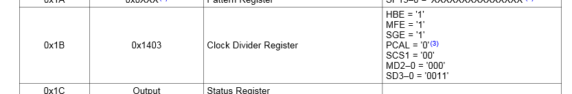
I read the papers on the product page, but I ve got the feeling that something there still is needed for work with both products. So is the delivered softwaretool "AMC1210 Evaluation" with options and parameters not full discribed. The same with  the other Board. I don´t know what setting is choosen on the chip. (Oversampling, freqeuncy, clock in or out).
Definitely not enough information for a evm board.
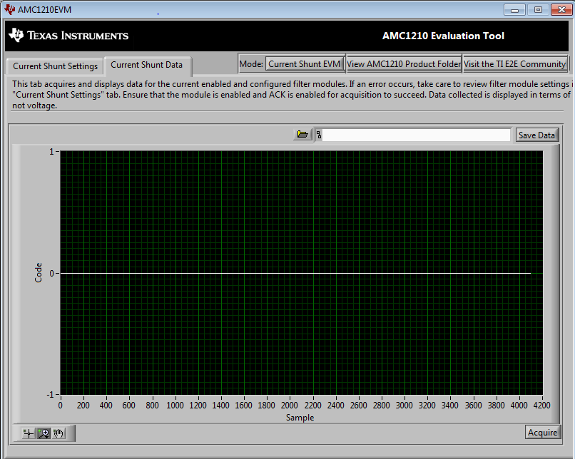
At the Moment it is possible to recive Data from the resolver, but not from the current shunt. It is always a error message to see after i kllick on "acquire". The message:
"Firmware encountered an unexpected failure, please try again."
I installed all software on a WIN7 PC SP1.
Please help me to find a solution. Best would be to send me the informations to fill the gaps from the sheets.

Regards,

Sebastian

  • Hi Sebastian,

    Welcome to the e2e forum!  Which AMC1305EVM did you get?  The CMOS versions should work with the AMC1210 evm once you wire the boards together through either J3 or J4.  The schematics for both EVM's are in the back of their respective users guides.  On the AMC1210, J3 and J4 are wired in a parallel manor so that they both have the same pin out.  The AMC1305 expects you to provide a modulator clock, so the AMC1210 would need to set the registers for the clock as an output.  Pin 6 and pin 7 on J3 and J4 connect to the clock pins on the AMC1210, while pin 8 and 9 connect to the data inputs.

  • Setting

    Plot

    Circuit

    Hi Tom,
    thanks for your quick answer. It was not a CMOS Version. We ordered a lot of stuff and we mixed cardboard boxes together.
    The Connection was right and first signals can be measured and recieved. But still there are some gaps. I use for the beginning "AMC1210MB-EVM Evaluation Software".
    I want to recieve my bit-stream from the AMC1305EVM. I tried to measure a DC 0.250V over a simple Voltage divider Circuit(+5VDC;GND=0V;R1 V1=4.75V an R2 V2=0.25V). Later I tried it with a AC Signal(with 100kHz; Amplitude 3 Vpp; +2V DC Offset;) instead of 5V DC over the circuit.
    OSR stands for oversampling ratio. But the meaning of IOSR and SOSR in the tool are unknown.
    I tried over this setup to get some reliable Data.

    How can I send you here a picture or post it?

    Regards,

    Sebastian

  • Hi Sebastian,

    The LVDS version of the AMC1305 won't work properly with the AMC1210 - you would have to do a CMOS to LVDS conversion using something like the SN65LVDS179.  The SOSR register is for the sync filter (Sync Over Sampling Register).  The IOSR is for the integrator, which you don't need for basic operation of the AMC1305.  More detail on that can be found in the AMC1210 datasheet.

  • Hello Tom, I solved the problems. It depended on the wire. The wire was to bad for this application. Means too much noise coupling.

    Now I use a chip based on CMOS.

    My question is:

    The AMC1305 can only work with a cycle speed of 5 -20 Mhz, but my AMC1210EVM delivers a speed of 32MHz.

    I could measure it, but I don´t know how it work.

    Can you explain it? Could I influence the cycle speed from the 1210EVM for the AMC1305 over the Software, what I use(EVM TOOL)? Or only SOSR?

    Using the onboard ads1205 as a resolver. There I got a issue to understand how Clock Divider of the Modulator and Signalgenerator match with the instructions from "sbaaa144.pdf".

    There is no clock 000 - 111 and 0000 - 1111.

    For what is the "COSR" (Softwaretool)?

    What did I need to use this EVM-Board to measure the whole time and save data over maybe 1 minute.

    Regards,

    Sebastian

  • Hi Sebastian,

    The 32MHz clock is coming from the oscillator found on the AMC1210MB-EVM at Y2. The AMC1305 will work with the 32MHz clock, its performance may suffer though. The easiest way to approach this would be to use an external clock source from a function generator and connect that to J3 on the AMC1305EVM and the input connectors to the AMC1210MB-EVM, then configure the control parameter registers to use CLKx as an input. Also, the SBAA144 document was not written using the AMC1210MB-EVM, that document was published in 2006 and its author used an FPGA based setup with the AMC1210.