This thread has been locked.

If you have a related question, please click the "Ask a related question" button in the top right corner. The newly created question will be automatically linked to this question.

ADS1292R connectivity problems

Other Parts Discussed in Thread: ADS1292R, ADS1292

I am having a problem reading the ADS1292R test signal. Eventually I'd like to read the full ECG signal, but first I need to be able to read the test signal.

HW background: The ADS1292R chip is interfacing with a TIVA 129X series MCU thru SPI interface. The TIVA is running the TI RTOS version 2_14_00_10 OS.

In my HW design:

The ADS DRDY signal does not go into the MCU as an input (but is available only as a test point).

The ADS START & CLKSEL pins are tied to gnd. VrefP is tied to a couple of caps (10uF & 0.1uF) & VerfN is tied to gnd.

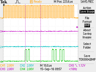
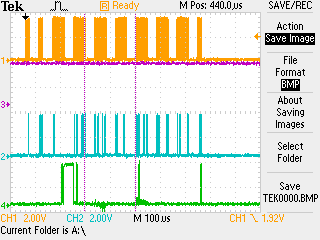
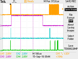
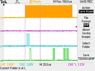
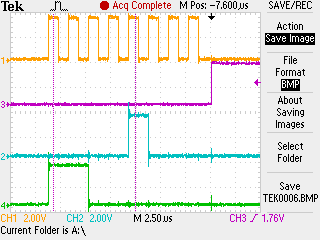
I have an external 2.048 MHz clock that drives the ADS chip. Because of this HW configuration I can’t wait for a DRDY rising edge to read the data. But I have injected enough delays in SW where I know that there is at least a 531 uS delay between the START cmd and the RDATA cmd. I also can’t read the data in continuous mode as my data has to be read every 5 mS so that it is synchronized to the other data collected in the system.

Here’s my ADS config code:

void       ConfigECGChip(void)

{

   // The order of register init is taken form Fig 63 of the ADS1292 data sheet


   // Our PWDN/RESET signal is provided by HW (U15:TPS3836K33) 200 ms after power up.

   // However, since this can be called at anytime, reset the chip via a cmd as well.

   // Reset all registers to default values before changing anything.


   SendECGCommand(ECG_RESET);


   // It takes 9xFmod cycles (70.3 uS) for the RESET cmd to complete. >>FA Measure wait

   for (wait= 0; wait < _9US_COUNTS; wait++) ;     // Wait added here for testing only.


   // ADS1292R device wakes up in the continuous mode. We must stop the continuous mode so the

   // registers can be written

   SendECGCommand(ECG_SDATAC);

   // Must wait 4xTclk cycles (31.25 uS) for the cmd to complete.

   // Wait 18 TClks (~8.8 uS given our 2.048 MHz clk)

   for (wait= 0; wait < _9US_COUNTS; wait++) ;


   WriteECGRegister( ECG_REG_CONFIG2, ECG_CONFIG2_TEST);

   // Wait for the reference to settle. Data sheet does not identify what the min wait time should be.

   for (wait= 0; wait < _9US_COUNTS; wait++) ;


   WriteECGRegister( ECG_REG_CONFIG1, ECG_CONFIG1_TEST );

   for (wait= 0; wait < _9US_COUNTS; wait++) ;


   // Set the clock divider for 2.048 MHz clock per sequence specification

   WriteECGRegister(ECG_REG_LOFF_STAT, ECG_LOFF_STAT_CLK_DIV_2048KHZ );

   for (wait= 0; wait < _9US_COUNTS; wait++) ;


   // Turn on the respiration demo mode

   WriteECGRegister(ECG_REG_RESP1, TEST_RESP_CONFIG );

   for (wait= 0; wait < _9US_COUNTS; wait++) ;


   // Configure channel 1 (Respiration) as powered down. (powered down + shorted inputs. See footnote 1 on pg 43 data sheet)

//   WriteECGRegister(ECG_REG_CH1SET, (ECG_CHAN_SET_PWR_DOWN + ECG_CHAN_SET_INPUT_SHORTED) ))

//   WriteECGRegister(ECG_REG_CH1SET, (ECG_CHAN_SET_INPUT_NORMAL) ))

//   WriteECGRegister(ECG_REG_CH1SET, (ECG_CHAN_SET_INPUT_TEMP) ))

   WriteECGRegister(ECG_REG_CH1SET, (ECG_CHAN_SET_INPUT_TEST) );

   for (wait= 0; wait < _9US_COUNTS; wait++) ;


//   WriteECGRegister(ECG_REG_CH2SET, (ECG_CHAN_SET_INPUT_NORMAL) ))

//   WriteECGRegister(ECG_REG_CH2SET, (ECG_CHAN_SET_PWR_DOWN) ))

   WriteECGRegister(ECG_REG_CH2SET, (ECG_CHAN_SET_INPUT_TEST) );

   for (wait= 0; wait < _9US_COUNTS; wait++) ;


   // Stop cmd is needed when switching form continuous to pulse mode.

   SendECGCommand(ECG_STOP);

   for (wait= 0; wait < _9US_COUNTS; wait++) ;

}


Here’s my ADS read code:

for (;;)

{

   // Measurement clock invokes this every MEASURE_CLOCK_INTERVAL (5 ms) period      

   Semaphore_pend (MeasureClockSem, BIOS_WAIT_FOREVER);


   SendECGCommand(ECG_START);


   // ECG chip settle time (between _START & _RDATA) is 531 uS. Delay injected for testing only.

   for (wait= 0; wait < ECG_SETTLE_TIME; wait++) ;


   SendECGCommand(ECG_RDATA);


   ch1Data[tDIndex] = ECGCh1Data;

   ch2Data[tDIndex] = ECGCh2Data;

   if( ++tDIndex >= 220)

       tDIndex = 0;

}

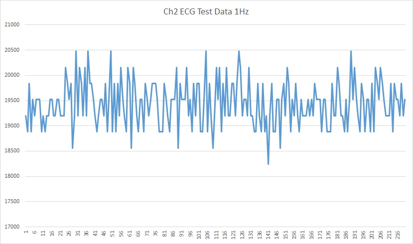
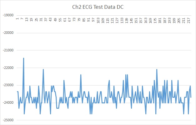
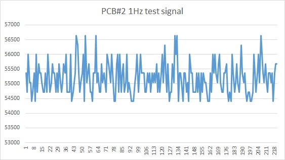
 I’ve tried to read the temperature, respiration or ECG test (1 Hz square wave) data, and all of that data that I read seems to be just noise. Can someone please look at the above code & HW design and determine what may be going wrong? Note that I can read the ADS chip registers and read them back correctly. I also know that I’m reading the correct chip ID (0x73) and the right ECG status (oxC00000)

  • Fred,

    I'm moving your post to the correct forum.
  • Hi Fred,

    Can you capture the SPI interface you are using with the ADS1292? That would be very helpful in trying to see what is going one here.
  • Hi Tom,

    Thasnk for responding to my question. Here are the SPI scope shots that you asked for.

    TEK000 is the picture of the 10 config cmds (I've read back each register and confirmed that the registers are in fact updated. I can provide more detail on each cmd if required.)

    TEK002 is the START cmd followed by RDATA

    TEK003 is the zoom  of the RDATA cmd where you can see the 0x0C0000 & RESP & ECG register values being reported back.

    TEK004 is further zoom of the RESP & ECG responses so you can see the CLK edges too.

    (Legend: Yel = CLK, CS= Not shown; Always active since this is a dedicated SPI bus, pink = DRDY, BLU = MOSI, GRN = MISO)

    Let me know if you want any more details,

    Fred

    P.S.

    You may notice that my SPI CLK is 500KHz. This is to make sure that I'm not pushing the ADS chip too hard. Eventually, I'd like to go up to 4 MHz.

  • Thank you Fred,

    So it looks like you are waiting for DRDY after a START command (a zoom of that would be nice), and since you are able to read the device ID I'll assume the SPI phasing is correct.  I would like to know exactly what you are writing to the various registers.  In your code snippet, it looks like you write only once to the CONFIG1 rgister, but I don't know what that value is.  What is the time between START commands?

  • Hi Tom,

    Sorry. I should have included all the variables being written to the various registers. Please see below. (In order)

    WriteECGRegister( ECG_REG_CONFIG2, 0xA3) // Internal ref + 1 Hz + test signal

    WriteECGRegister( ECG_REG_CONFIG1, 0x86 ) // chose /16 to minimize the settle time.

    WriteECGRegister(ECG_REG_LOFF_STAT, 0x40 ) // 2 MHZ external clk

    WriteECGRegister(ECG_REG_RESP1, 0xC0 ) // demo En + demo En1. I don't care about resp, and can turn this off if needed.

    WriteECGRegister(ECG_REG_CH1SET, 0x05)  // test input

    WriteECGRegister(ECG_REG_CH2SET, 0x05)  // test input

    As for the DRDY timing, I'm not waiting for the DRDY rising edge after the start. (It's not an input to my MCU) Immediately after the START cmd, the ADS asserts the DRDY high for ~516 uS. I wait another ~100uS before I send the RDATA cmd. (See TEK0002 bitmap) (The timings are purposely larger than needed to eliminate any potential timing problems.) Finally, the START cmds are repeated every 5 mS which is the task's clock interval. (I can extend this for testing if needed, but it has to work @ 5mS eventually.)

  • Hi Fred,

    Thanks for the START zoom and the detail on the register contents!

    I don't see anything in what you've provided that would cause you to see 'just noise' when trying to read the test signal or temp sensor. The test signal is 1 Hz and by all accounts you should be seeing something on the back end. Can you plot out the array for us? Have you verified (by stepping through your code) that the array index is advancing as you expect it to?
  • Hi Tom,

    I picked an array of 220 elements to store the ECG results. At my 5 mS sample time, this works out to be 1100 mS. So I should see a 1Hz signal. I see on the scope that the task gets called every 5mS, and STARTs conversion & reads the ECG data as expected. The index also increments so the cyclical buffer does not lose results. I copied the 220 results from the Ch2 ECG buffer into a text file, then imported it to Excel. Below is plot. Vertical access is the reported ECG test value. As you can see values are all over the place and I don't see a decipherable pattern.

    Something that surprises me is that the reported values are always 2 bytes! That first (MSB) byte is always 0. What is the typical range of data that one should see under the 1Hz test output? the manual says +- (VrefP - VrefN) / 2400. I'm clearly not seeing a negative #. I'm using internal reference and my refP pin is tied to a cap. What should I be reading?

    I'm also planning on repeating this on another target PCB to see if I have a HW problem of some sort. Any other ideas of things to investigate?

    Below is the plots of 1 Hz signal and DC signal both. Interestingly, the DC signal is always negative. Is that a clue?

  • Update: This AM, I ran the same experiment on a second PCB. The results are similar, though the mean raw value is larger than in PCB #1. (55,300 vs 19,500) So I don't think that I have a HW problem with one PCB.

  • Hi Fred,

    Are you able to provide any raw data from the ADS1292?
  • Hi Tom,

    I may not understand your question fully. But let me answer in this way: As I mentioned before, I am able to read the chip ID (0x73) correctly (So my SPI phasing is correct.) I also read the correct status bytes (0xC00000) before the Ch1 & Ch2 garbage bytes are read.

    While experimenting with the chip, I removed the "Single shot" bit mask in Config 1 register, and placed the chip in continuous mode at the end of my configuration routine. In the continuous mode, I'm able to read back the 1 Hz test signal. (See below). I have an ECG simulator, and will try to read the full ECG in continuous mode as well.  However, for my final product, I need to be able to read the ECG values in the single shot mode. Unfortunately, there does not seem to be a clear path of how to do that. It would be nice if TI had an initialization sequence, similar to Figure #63 pg. 63, for the one shot mode as well. It is not at all obvious what things can be done in continuous mode and which ones can be done in one shot mode.

    -Fred

  • Hi Fred,

    Very interesting...were you still running the same routine otherwise?  What I was looking for is the raw conversion results from the ADS1292, before doing any data manipulation.

  • Hi Tom,

    Yes, I was running the same exact routine where I issued a RDATA cmd every 5 mS. The only difference was the ADS initialization code that I mentioned.

    As for the raw conversion data: The graphs that I provided are the raw data returned from the ADS chip. I download and start running the code. After a few seconds when I've confirmed the right SPI pattern on the scope, I stop the code execution and export the data collected in the ch2Data array (1.1 - 2 seconds worth) into a text file. Finally the text file is imported to Excel and converted to a line chart which are attached to my replies that you see. the #s on the X axis represents time (in 5 mS ticks) and Y axis is the raw values as reported by the ADS. I've performed no data manipulation on the received data. Would you like to see the text file containing the raw data?

    Since yesterday, I tried doing the same (go into continuous mode at the end of configuration) and program the ADS for normal mode ( actual ECG signal inputs). I see on the scope that the DRDY signal has a falling edge every 500uS (2KHz sampling). But the RDATA cmds in this case do not receive any meaningful ECG values, rather just noise. I've programmed my ECG simulator to output sq wave, sine wave and ECG of various rates. While I verify on the scope that the ECG simulator is generating the correct composite signal, the individual signals that go to the chip (Left Leg, Right Leg, Right Arm, Left Arm) just generate noise.

    Fred
  • Hi Fred,

    Can I send you an e-mail at the address on your profile?  I'd like to give you a call to discuss your application in a bit more detail.

  • Tom,

    Yes, please! I was thinking of the same thing. Send me an email and I'll share my phone contact information with you.

    The only thing is that I am away from the office today. But we can talk tomorrow if that works for you.

    Fred