This thread has been locked.

If you have a related question, please click the "Ask a related question" button in the top right corner. The newly created question will be automatically linked to this question.

ADS131A04 - Not acknowledging any commands

Other Parts Discussed in Thread: ADS131A04EVM, ADS131A04

Greetings!

I'm using the ADS131A04EVM and I'm trying to interface the ADC chip to Odroid C1+. However, the chip doesn't respond to any of the commands that I send and instead, all I'm able to read is 0x1. It doesn't send me anything else, regardless of what I transmit.

For reference here is the EVM configuration I'm using:
I've shorted the JP1 header to enable external digital signals (hold the on board processor in RESET and disable the level shifter).
I've also switched S4 down for manual control of the ADC chip's mode pins:
M0: pins 1 and 2 connected (IOVDD) for asynchronous interrupt mode
M1: pins 1 and 2 connected (IOVDD) for 32 bit word size
M2: pins 2 and 3 connected (GND) for no hamming code
Other switches and headers are left to their default positions (sbau259)
Reference voltage is EVM board generated reference voltage and adc input signal is 1.2V DC. (Though I don't think this matters for my problem)
Lastly, the board uses USB power for both analog and digital power supplies.

SPI wiring:
The schematics showed that there already is a pull-up resistor connected to MISO so I didn't bother to add anymore pull-ups when I wired the two modules together.

I wrote the code below for initializing the adc chip. I've made sure to set SPI mode to 1, word size to 32 bits, and frame length to 1 word (since the ads131a04 uses dynamic frame size by default). I used 1MHz SCLK frequency which is far from the chip's max (25MHz). The datasheet specified that when in 32 bit mode, the 16 bit commands to be sent should have their LSBs padded with zeroes, I've followed that too (ie. 0x00110000 for RESET command).

I've tried isolated tests to see if both components that I'm using are working. For the ADS131A04 chip, I tested it by re-enabling the on board processor and running the TI program that came with it. It was working fine. For the Odroid C1+, I tested the code above (with minor changes like SPI settings and commands) with the ArduCAM Mini and I was able to communicate with it through SPI.

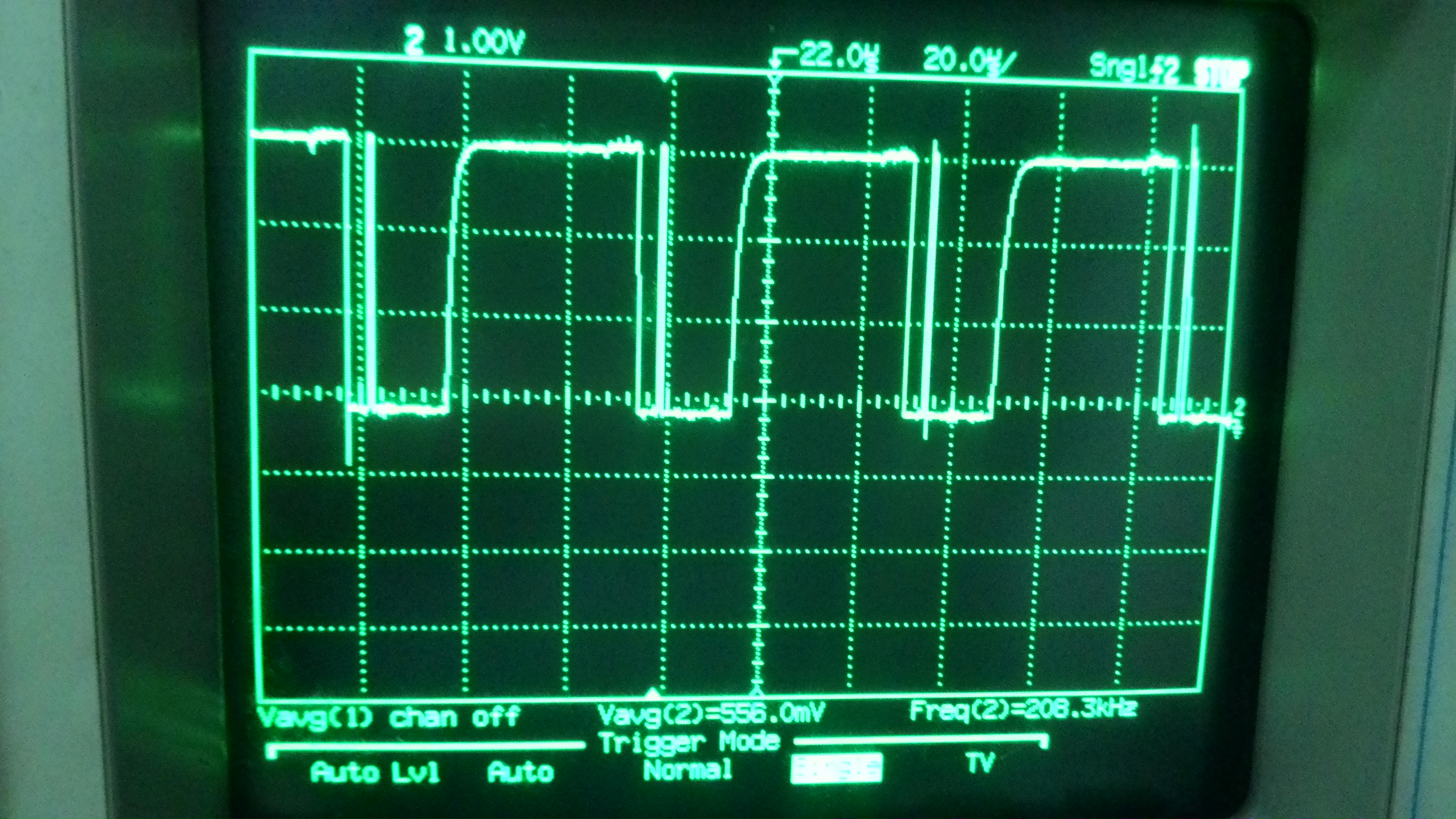
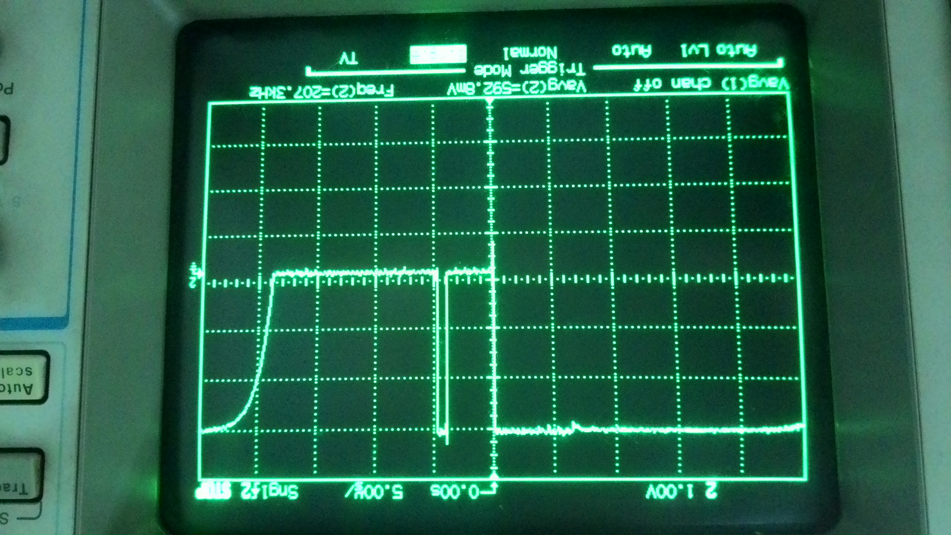
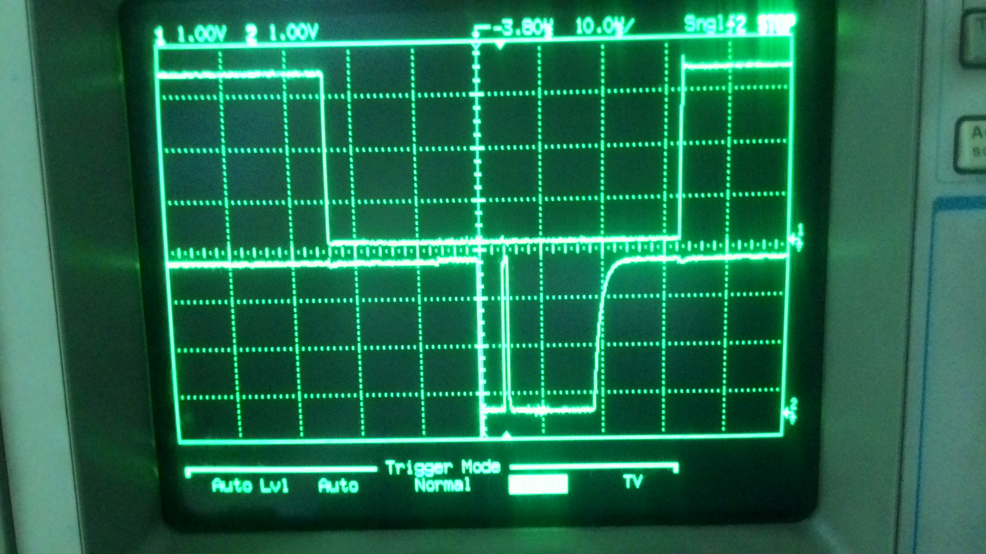
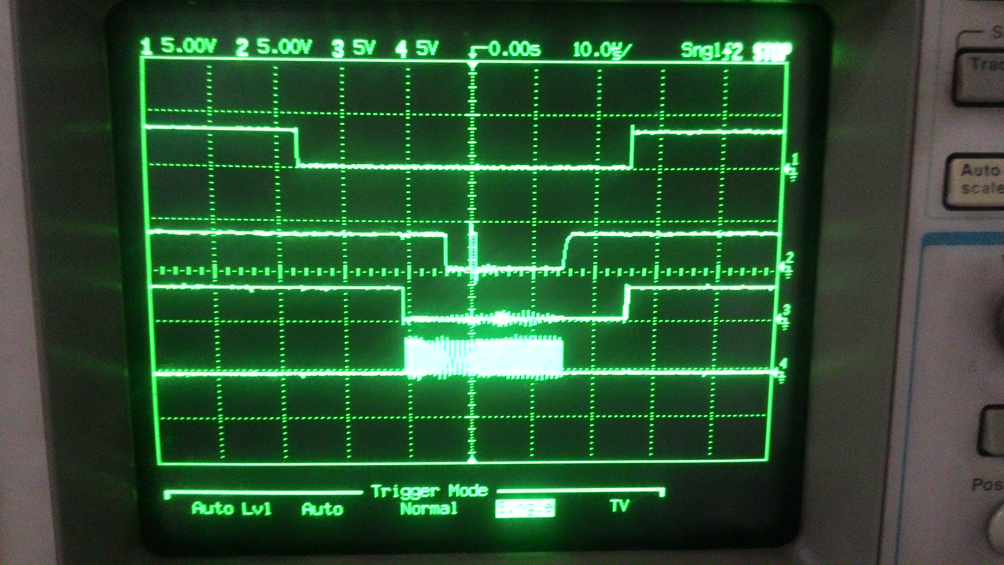
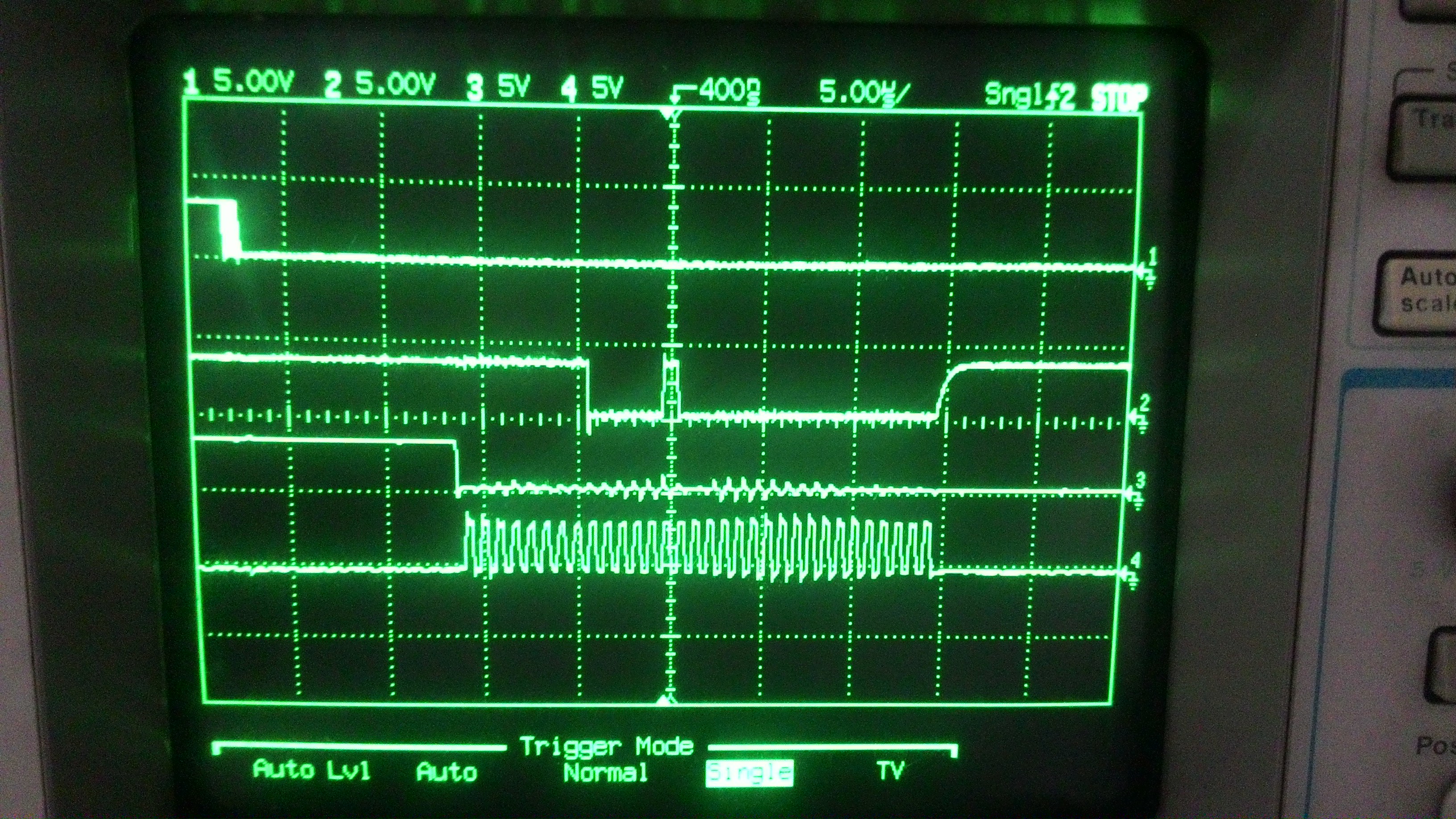
I'm only using a really old 100Mhz analog oscilloscope to check the signals and I can't actually see the bit by bit waveform being transmitted/received (the signal isn't stable). I've checked the forum but the existing thread which almost had the same problem that I had doesn't have an answer (nobody replied to it yet and it's been posted about a month ago). I've ran out of ideas for tests to pinpoint where I went wrong. Any suggestions? Thanks in advance!

/* 	SPI interface for ADS131a04
 *	SPI Mode: 1
 *	Sampling rate: 500 sps
 *	Bit per word: 32 bits
 */

#include <stdint.h>
#include <unistd.h>
#include <stdio.h>
#include <stdlib.h>
#include <getopt.h>
#include <fcntl.h>
#include <sys/ioctl.h>
#include <linux/types.h>
#include <linux/spi/spidev.h>

#define ARRAY_SIZE(a) (sizeof(a) / sizeof((a)[0]))

static void pabort(const char *s) {
	perror(s);
	abort();
}

/***	SPI variables initialization	***/
static const char *device = "/dev/spidev0.0";
static uint8_t mode = SPI_MODE_1;
static uint8_t bits = 32;
static uint32_t speed = 1000000;
//static uint16_t delay;
static uint16_t delay = 1;		//Check CS behavior per transfer first
static uint8_t deselect_cs = 1;


static void waitForADCReady(int fd) {
	int ret;
	uint32_t tx[1] = {0};
	uint32_t rx[ARRAY_SIZE(tx)] = {0, };
	struct spi_ioc_transfer tr = {
		.tx_buf = (unsigned long)tx,
		.rx_buf = (unsigned long)rx,
		.len = ARRAY_SIZE(tx),
		.delay_usecs = delay,
		.speed_hz = speed,
		.bits_per_word = bits,
	};

	printf("Waiting for READY...\n");
	while (1) {
		ret = ioctl(fd, SPI_IOC_MESSAGE(1), &tr);
		if (ret < 1)
			pabort("can't send spi message");

		printf("0x%x\n", rx[0]);

		if(rx[0] == 0xFF040000) {
			printf("0x%x", rx[0]);
			break;
		}
	}
}

void sendADCcommand(int fd, uint32_t command, uint32_t status) {
	int ret;
	int i = 0;
	uint32_t tx[1] = {0};
	uint32_t rx[ARRAY_SIZE(tx)] = {0, };
	struct spi_ioc_transfer tr = {
		.tx_buf = (unsigned long)tx,
		.rx_buf = (unsigned long)rx,
		.len = ARRAY_SIZE(tx),
		.delay_usecs = delay,
		.speed_hz = speed,
		.bits_per_word = bits,
		//.cs_change = deselect_cs,
	};

	tx[0] = command;
	printf("Sending command = 0x%x\n", tx[0]);
	ret = ioctl(fd, SPI_IOC_MESSAGE(1), &tr);
	if (ret < 1)
		pabort("can't send spi message");

	tx[0] = 0;
	printf("Waiting for acknowledgement = 0x%x...\n", status);
	while (1) {
		ret = ioctl(fd, SPI_IOC_MESSAGE(1), &tr);
		if (ret < 1)
			pabort("can't send spi message");

		if (i == 10000) {
			printf("tx = 0x%x, rx = 0x%x\n", tx[0], rx[0]);
			i = 0;
		}

		if(rx[0] == status) {
			printf("0x%x", rx[0]);
			break;
		}

		i++;
	}
}

void readADCdata(int fd, float* ADCvalues) {
	int ret, i;
	uint32_t tx[5] = {0, 0, 0, 0, 0};
	uint32_t rx[ARRAY_SIZE(tx)] = {0, };
	struct spi_ioc_transfer tr = {
		.tx_buf = (unsigned long)tx,
		.rx_buf = (unsigned long)rx,
		.len = ARRAY_SIZE(tx),
		.delay_usecs = delay,
		.speed_hz = speed,
		.bits_per_word = bits,
		//.cs_change = deselect_cs,
	};

	ret = ioctl(fd, SPI_IOC_MESSAGE(1), &tr);
	if (ret < 1)
		pabort("can't send spi message");

	for (i = 0; i < 3 ; i++) {
		*(ADCvalues + i) = rx[i+1] >> 8;				//data is 24 bits left aligned on a 32 bit word
		*(ADCvalues + i) *= (float) 2.5/8388608;						//ADC conversion factor
	}
}

int main(int argc, char	*argv[]) {
	int ret = 0;
	int fd;

	fd = open(device, O_RDWR);
	if (fd < 0)
		pabort("can't open device");

	/***	SPI mode init	***/
	ret = ioctl(fd, SPI_IOC_WR_MODE, &mode);
	if (ret == -1)
		pabort("can't set spi mode");

	ret = ioctl(fd, SPI_IOC_RD_MODE, &mode);
	if (ret == -1)
		pabort("can't get spi mode");

	/***	Set bits per word	***/
	ret = ioctl(fd, SPI_IOC_WR_BITS_PER_WORD, &bits);
	if (ret == -1)
		pabort("can't set bits per word");

	ret = ioctl(fd, SPI_IOC_RD_BITS_PER_WORD, &bits);
	if (ret == -1)
		pabort("can't get bits per word");

	/***	Set max speed hz	***/
	ret = ioctl(fd, SPI_IOC_WR_MAX_SPEED_HZ, &speed);
	if (ret == -1)
		pabort("can't set max speed hz");

	ret = ioctl(fd, SPI_IOC_RD_MAX_SPEED_HZ, &speed);
	if (ret == -1)
		pabort("can't get max speed hz");

	printf("spi mode: %d\n", mode);
	printf("bits per word: %d\n", bits);
	printf("max speed: %d Hz (%d KHz)\n", speed, speed/1000);

	//waitForADCReady(fd);
	sendADCcommand(fd, 0x00110000, 0xFF040000);			//send RESET command and wait for READY
	sendADCcommand(fd, 0x06550000, 0x06550000);			//unlock ADC
	sendADCcommand(fd, 0x4D020000, 0x2D020000);			//set CLK1 register
	sendADCcommand(fd, 0x4E400000, 0x2E400000);			//set CLK2 register
	sendADCcommand(fd, 0x4F0F0000, 0x2F0F0000);			//enable ADC
	sendADCcommand(fd, 0x00330000, 0x00330000);			//wakeup ADC
	sendADCcommand(fd, 0x05550000, 0x05550000);			//lock registers
	

	/***	Data acquisition part	***/
	
	//float* ADCvalues;
	//readADCdata(fd, ADCvalues);
	
	printf("Done! \n");
	close(fd);

	return ret;
}

  • Karol,

    Do you every get the "READY" word from the A04 once you power on the ADC? After receiving it, do you send the UNLOCK command? 0x1 is a strange response given that it corresponds to none of the system responses one could recieve. Is there any way you could look at the SPI interface with a logic analyzer or oscilloscope and see each bit?

    Regards,
    Brian Pisani
  • Hi Brian,

    I'm not able to get any other response from the A04 aside from 0x1. The circumstances to which I've tested this are listed below:
    1. Power on the board, wait for a few minutes, then run my code which would wait for the READY word. Result is I get 0x1. I've tried waiting for about 5 minutes while the code is running but there were no changes to the result, so I aborted.
    2. Power on the board, wait for a few minutes, then run my code which would send first a RESET command then wait for the READY word. Same result. I wait for a few minutes to see if anything changes, there were none, so again, I aborted.
    3. Power on the board, wait for a really long time (around 10-20 mins so that I can assume the chip is ready by then), then run my code which would send an UNLOCK command. The status response of the chip should be different then, but still, what I received was a 0x1.

    I've hooked up the MISO line to an oscilloscope while my code is running in a loop of transmitting zeroes. I needed to do this so that I could see the waveform since I don't have a logic analyzer, plus the "roll" time feature of the oscilloscope can only go as small as 200ms/div (I've tried using this and it's too fast to actually be able to read the bits). What I saw was consistent with the results I've gathered, a single pulse every period. I don't have a picture right now but I'll attach one as soon as possible (tomorrow around noon).
  • Hello Karol,

    Are your transactions with the A04 synchronous to DRDY? Do you wait for DRDY, send the NULL command, then wait for the next frame to send another command and receive acknowledgement for the first command? I could not see where in your code you wait for the DRDY signal. The transaction should look like the following image where DRDY dictates the "Data Frame".

    ADS131A02 ADS131A04 User_command_ACK_sbas590.gif
    I am interested to see some images from your oscilloscope.

    Regards,

    Brian Pisani

  • Hi Brian,

    You're right. My code doesn't wait for the DRDY signal, I thought it would only be relevant after I've finished initializing the chip and enabled the ADC. I'll try implementing that and see if it fixes the problem, I'll update again asap. Many thanks!

    Also, here is the MISO line as seen using the oscilloscope.

    Zoomed in to 5us/div

  • Hi Brian,

    I've synchronized the SPI communication to the DRDY signal from the A04. It still didn't solve the problem. The datasheet says that when in asynchronous interrupt mode, the DRDY would go from high to low, signalling new data ready. I've edited my code below to wait for that high to low edge trigger before sending and receiving any data from the adc chip. All I'm able to read is still 0x1, regardless of the command I send.

    /* 	SPI interface for ADS131a04
     *	SPI Mode: 1
     *	Sampling rate: 500 sps
     *	Bit per word: 32 bits
     */
    
    #include <stdint.h>
    #include <unistd.h>
    #include <stdio.h>
    #include <stdlib.h>
    
    #include <getopt.h>
    
    #include <fcntl.h>
    #include <sys/ioctl.h>
    #include <linux/types.h>
    #include <linux/spi/spidev.h>
    
    #include <wiringPi.h>
    
    #define ARRAY_SIZE(a) (sizeof(a) / sizeof((a)[0]))
    
    static void pabort(const char *s) {
    	perror(s);
    	abort();
    }
    
    /***	SPI variables initialization	***/
    static const char *device = "/dev/spidev0.0";
    static uint8_t mode = SPI_MODE_1;
    static uint8_t bits = 32;
    static uint32_t speed = 1000000;
    //static uint16_t delay;
    static uint16_t SPIdelay = 1;		//Check CS behavior per transfer first
    static uint8_t deselect_cs = 1;
    
    
    static void waitForADCReady(int fd) {
    	int ret;
    	int i = 0;
    	uint32_t tx[1] = {0};
    	uint32_t rx[ARRAY_SIZE(tx)] = {0, };
    	struct spi_ioc_transfer tr = {
    		.tx_buf = (unsigned long)tx,
    		.rx_buf = (unsigned long)rx,
    		.len = ARRAY_SIZE(tx),
    		.delay_usecs = SPIdelay,
    		.speed_hz = speed,
    		.bits_per_word = bits,
    	};
    
    	printf("Waiting for READY...\n");
    	while (1) {
    		/***	Wait for DRDY high to low	***/
    		if (digitalRead(7) == 0) {
    			while(digitalRead(7) == 0);
    		}
    		while(digitalRead(7) == 1);
    
    		ret = ioctl(fd, SPI_IOC_MESSAGE(1), &tr);
    		if (ret < 1)
    			pabort("can't send spi message");
    
    		if (i == 5000) {
    			printf("0x%x\n", rx[0]);
    			i = 0;
    		}
    
    		if(rx[0] == 0xFF040000) {
    			printf("0x%x", rx[0]);
    			break;
    		}
    
    		i++;
    	}
    }
    
    void sendADCcommand(int fd, uint32_t command, uint32_t status) {
    	int ret;
    	int i = 0;
    	uint32_t tx[1] = {0};
    	uint32_t rx[ARRAY_SIZE(tx)] = {0, };
    	struct spi_ioc_transfer tr = {
    		.tx_buf = (unsigned long)tx,
    		.rx_buf = (unsigned long)rx,
    		.len = ARRAY_SIZE(tx),
    		.delay_usecs = SPIdelay,
    		.speed_hz = speed,
    		.bits_per_word = bits,
    //		.cs_change = deselect_cs,
    	};
    
    	tx[0] = command;
    	printf("Sending command = 0x%x\n", tx[0]);
    
    	/***	Wait for DRDY high to low	***/
    	if (digitalRead(7) == 0) {
    		while(digitalRead(7) == 0);
    	}
    	while(digitalRead(7) == 1);
    
    	ret = ioctl(fd, SPI_IOC_MESSAGE(1), &tr);
    	if (ret < 1)
    		pabort("can't send spi message");
    
    	tx[0] = 0;
    	printf("Waiting for acknowledgement = 0x%x...\n", status);
    	while (1) {
    		/***	Wait for DRDY high to low	***/
    		if (digitalRead(7) == 0) {
    			while(digitalRead(7) == 0);
    		}
    		while(digitalRead(7) == 1);
    
    		ret = ioctl(fd, SPI_IOC_MESSAGE(1), &tr);
    		if (ret < 1)
    			pabort("can't send spi message");
    
    		if (i == 5000) {
    			printf("tx = 0x%x, rx = 0x%x\n", tx[0], rx[0]);
    			i = 0;
    		}
    
    		if(rx[0] == status) {
    			printf("0x%x", rx[0]);
    			break;
    		}
    
    		i++;
    	}
    }
    
    void readADCdata(int fd, float* ADCvalues) {
    	int ret, i;
    	uint32_t tx[5] = {0, 0, 0, 0, 0};
    	uint32_t rx[ARRAY_SIZE(tx)] = {0, };
    	struct spi_ioc_transfer tr = {
    		.tx_buf = (unsigned long)tx,
    		.rx_buf = (unsigned long)rx,
    		.len = ARRAY_SIZE(tx),
    		.delay_usecs = SPIdelay,
    		.speed_hz = speed,
    		.bits_per_word = bits,
    		//.cs_change = deselect_cs,
    	};
    
    	/***	Wait for DRDY high to low	***/
    	if (digitalRead(7) == 0) {
    		while(digitalRead(7) == 0);
    	}
    	while(digitalRead(7) == 1);
    
    	ret = ioctl(fd, SPI_IOC_MESSAGE(1), &tr);
    	if (ret < 1)
    		pabort("can't send spi message");
    
    	for (i = 0; i < 3 ; i++) {
    		*(ADCvalues + i) = rx[i+1] >> 8;				//data is 24 bits left aligned on a 32 bit word
    		*(ADCvalues + i) *= (float) 2.5/8388608;						//ADC conversion factor
    	}
    }
    
    int main(int argc, char	*argv[]) {
    	int ret = 0;
    	int fd;
    
    	wiringPiSetup();
    	pinMode(7, INPUT);
    
    	fd = open(device, O_RDWR);
    	if (fd < 0)
    		pabort("can't open device");
    
    	/***	SPI mode init	***/
    	ret = ioctl(fd, SPI_IOC_WR_MODE, &mode);
    	if (ret == -1)
    		pabort("can't set spi mode");
    
    	ret = ioctl(fd, SPI_IOC_RD_MODE, &mode);
    	if (ret == -1)
    		pabort("can't get spi mode");
    
    	/***	Set bits per word	***/
    	ret = ioctl(fd, SPI_IOC_WR_BITS_PER_WORD, &bits);
    	if (ret == -1)
    		pabort("can't set bits per word");
    
    	ret = ioctl(fd, SPI_IOC_RD_BITS_PER_WORD, &bits);
    	if (ret == -1)
    		pabort("can't get bits per word");
    
    	/***	Set max speed hz	***/
    	ret = ioctl(fd, SPI_IOC_WR_MAX_SPEED_HZ, &speed);
    	if (ret == -1)
    		pabort("can't set max speed hz");
    
    	ret = ioctl(fd, SPI_IOC_RD_MAX_SPEED_HZ, &speed);
    	if (ret == -1)
    		pabort("can't get max speed hz");
    
    	printf("spi mode: %d\n", mode);
    	printf("bits per word: %d\n", bits);
    	printf("max speed: %d Hz (%d KHz)\n", speed, speed/1000);
    
    	waitForADCReady(fd);
    //	sendADCcommand(fd, 0x00110000, 0xFF040000);			//send RESET command and wait for READY
    	sendADCcommand(fd, 0x06550000, 0x06550000);			//unlock ADC
    	sendADCcommand(fd, 0x4D020000, 0x2D020000);			//set CLK1 register
    	sendADCcommand(fd, 0x4E400000, 0x2E400000);			//set CLK2 register
    	sendADCcommand(fd, 0x4F0F0000, 0x2F0F0000);			//enable ADC
    	sendADCcommand(fd, 0x00330000, 0x00330000);			//wakeup ADC
    	sendADCcommand(fd, 0x05550000, 0x05550000);			//lock registers
    	
    	/***	Data acquisition part	***/
    	
    	//float* ADCvalues;
    	//readADCdata(fd, ADCvalues);
    	
    	printf("Done! \n");
    	close(fd);
    
    	return ret;
    }
    

    Also, shown here is the DRDY line (channel 1) and the MISO line (channel 2). The results are consistent with what I'm able to read.

    Do you have other suggestions that I could try to fix this? Thank you very much!

  • Karol,

    Do you have more channels on your oscilloscope to monitor CS and SCLK?

    Brian
  • Hi Brian,

    Here are the waveforms for DRDY (channel 1), MISO (channel 2), CS (channel 3), and SCLK (channel 4).

    Zoomed in to 5us/div. I can't fit the part where DRDY and CS go high, but it was shown in the 10us/div picture above that they indeed go high after a while.

    Edit: I just realized that after reading the bits that it is indeed 0xFF040000, but for some reason my code (or the odroid) reads it as 0x1. I'll review my code again and see what the culprit is. Thanks for the help!

    Edit2: But the other half of the problem still persists. I've tried sending other commands (ie. UNLOCK command) in a continuous loop but the result is still 0xFF040000. What could be the problem?

  • Hey Karol,

    It's clear that the device is sending the READY word. To understand why it will not send anything else, please capture MOSI sending the UNLOCK command (0x0655) along with SCLK.

    Regards,
    Brian