This thread has been locked.

If you have a related question, please click the "Ask a related question" button in the top right corner. The newly created question will be automatically linked to this question.

DAC80004 EVM

Other Parts Discussed in Thread: DAC80004

Hi Everyone,

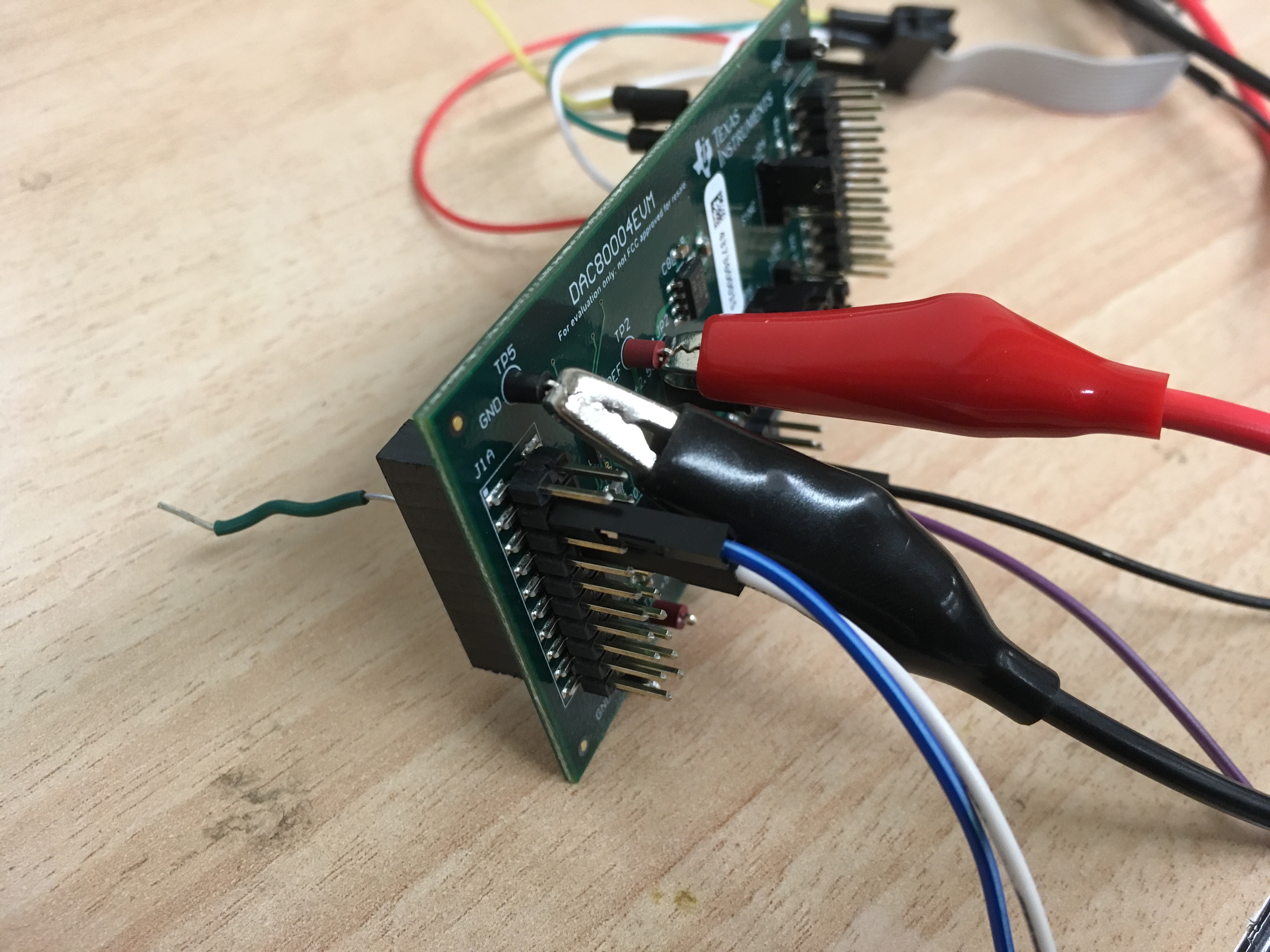
I am currently testing the DAC80004 with the DAC80004 EVM.

There are 2 strange things that i noticed and could not  be understood by me.

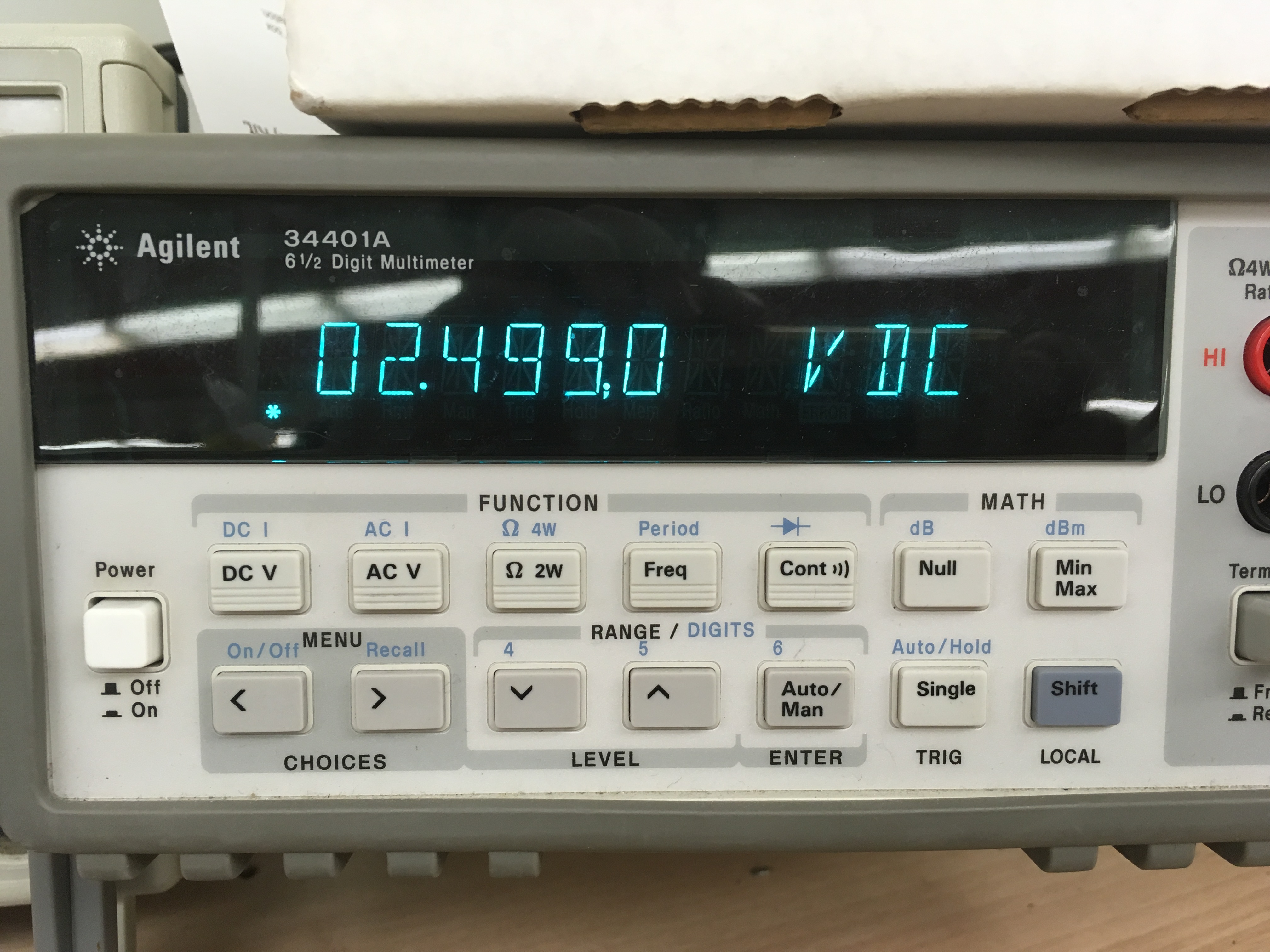
1) The board has a onboard 2.5V reference. But when i measured the reference voltage(TP2), I am getting 2.499V

But when i set the voltage to max. (02 0F FF FF), I am getting 2.4998 V which is higher than the reference voltage i measured, The precision 4 digital after decimal point is important to me.

If i use 2.4998 to calculate the output voltage, The output is somewhat accurate and The voltage error is maxed around 0.2mV.(Is this expected performance ?)

But if i used 2.499 to do the calculations, The error is much larger.

2) Also for the on board 5V reference ,The measured reference voltage at TP2 is exactly 5V. The max output is 5.0003V which is higher than the reference

I think the DAC meets my accuracy requirement, But i would like to know what is going on,

Thanks,

Eddy

  • Howdy Eddy,

    I don't see anything from Figure 51 of the Datasheet that would suggest that it is possible to output a voltage value higher than the reference input.  After some quick searching I did notice that the accuracy of the 34401A may be impacting your measurements.

    According the 34401 literature, which I found at:

    cp.literature.agilent.com/.../5968-0162EN.pdf

    The DC accuracy of the system for a 10V Range (10V is lowest range that can be used for 2.5 or 5V measurement) is 0.0015 + 0.0004V for a 1-24hr warmup.  Therefore the accuracy of the measurement tool may be affecting measurement results as it only has a resolution of 1.5mV.

    Would you happen to have access to a 8.5 digit multimeter, such as the HP3458A?  If possible, please repeat the above experiments with this tool for accurate results.

    Best Regards,

    Matt

  • Eddy,

    It looks like I may have spoke to soon, after reviewing the 34401 literature I noticed that the accuracy was expressed as a percentage of the range, which in this case would be 10V*0.0015%. This of course would be the accuracy for a 10V Range. Can you verify that this range is the correct range used for the measurements?

    Best Regards,
    Matt
  • Hi Matt

    I am using the 10V range. I do not think it is the issue with multimeter. Since I was able to measure the output from DAC with error less than 0.2mV

    It is really strange for me. It seems to be the reference I measured can not be used to calculate. ADC output . It worries me a lot

  • Eddy,

    What supply voltage is being used for VDD? How is this voltage and it's ground being applied to the board? Could you give us any other details as well about the other connections? At this point our next step would be to try this out with the EVM board ourselves in the lab to try and track down root cause.

  • Hi Kevin, I put the VDD to be a bit above 5V, (~5.1V) to get the correct 5V reference. The ground is supplied.
    I noticed this behavior for both reference voltage, The max output is alway higher than the reference voltage.

    I supplied the power and ground from the Agilent power supply and used the Total phase USB to SPI convertor to talk to the Board.
    Other than those connections, The voltage is measured as the picture showed.

    Thanks,
    Eddy
  • Eddy,

    When you say "the max output is always higher than the reference voltage" I assume your sample size is just this one EVM? Since you have greater than 5V analog supply voltage the output amplifiers on the DAC80004 have some additional headroom which makes >5V outputs possible. The device is specified with maximum gain error of +/- 0.05% FSR which means it is possible for the full-scale output voltage to be both greater than and less than the reference voltage by up to 2.5mV with a 5V reference. There could also be some impact of offset error at full-scale, the cumulative effects of offset and gain errors are summarized with the full-scale error specification of +/-0.07% FSR max, meaning at full scale you could see up to 3.75mV greater than or less than the reference voltage.

    The issues you see with the reference voltage changing at full-scale versus zero-scale DAC output is more than likely a layout issue as opposed to a device issue. We will take a look at this on the EVM board ourselves in the TI labs. If it is a layout issue it could very well have something to do with the particular connection and setup that you have the board in using the externally wired connectors. We will keep you posted. Thanks for your patience.
  • Howdy Eddy,

    One thing to add to the post above is that the reference is divided down within the part, and a gain stage is responsible for implementing the final full-scale range.  The errors associated with the gain stage is included in the datasheet and was described in Kevin's post above.  To restate, the full-scale error specification of +/-0.07%FSR includes this error, which does mean that for a 2.5V reference you can possibly view a +/- 1.75mV error, while a 5V reference produces +/-3.5mV error.

    I've run an experiment in our labs with the following conditions and obtained the results described and shown in the images below:

    Conditions:

    VDD: 5.1V

    On board 2.5V reference

    Cases:

    1) Measurement of 2.5V reference with both 33401A and HP3458A multimeter: (* The HP3458A PLC was increased to perform more averaging on the measured voltage giving use a more accurate result)

    2) Measurement of full-scale output of DAC 0xFFFF using both the 33401A and HP3458A multimeter.

  • Hi Matt and Kevin,

    "I assume your sample size is just this one EVM",

    Yeah, It is just 1 EVM.

    Thanks a lot for verifying this. It seems to be some issues other than the board.

    maybe it is the SPI host ? (I do have to tie the ground of the SPI host to the board ground.)

    At this point, I do not have any theory why this is the case for my board. We are designing the board this week.
    and will tested the board out once we completed it. Hope this is most likely a isolated case.


    Thanks a lot for your help,
    Eddy
  • Hello Eddy,

    I verified the above on 2 EVMS, both produced similar results.  To get a better understanding of your current setup you may want to switch you readings to manual and use 6 digit resolution.  Depending on where your measurement takes place, yes you may want to connect the digital ground to the board ground if measuring digital signals referenced on the EVM.

    Best Regards,

    Matt