This thread has been locked.

If you have a related question, please click the "Ask a related question" button in the top right corner. The newly created question will be automatically linked to this question.

Heavy noise when plotting ECG from ADS1293

Other Parts Discussed in Thread: ADS1293, CC2541, TIDA-00096

I am working on a slightly modified project TIDA-00096 (CC2541 + ADS1293) with originally provided firmware. Since I have been receiving very noisy ECG data from human body when plotting it in Android app, I have attached function waveform generator to various combinations directly to electrodes. I have skipped some combinations though, since there wasn't any change in the signal with different waveform settings.

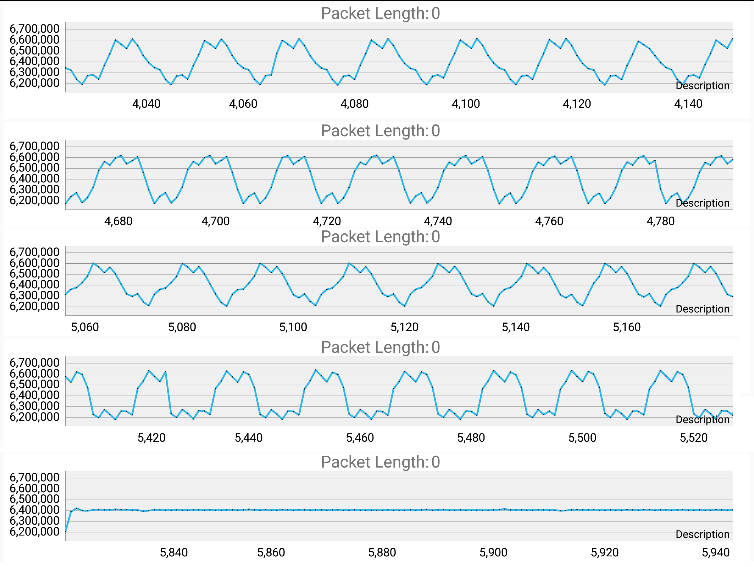
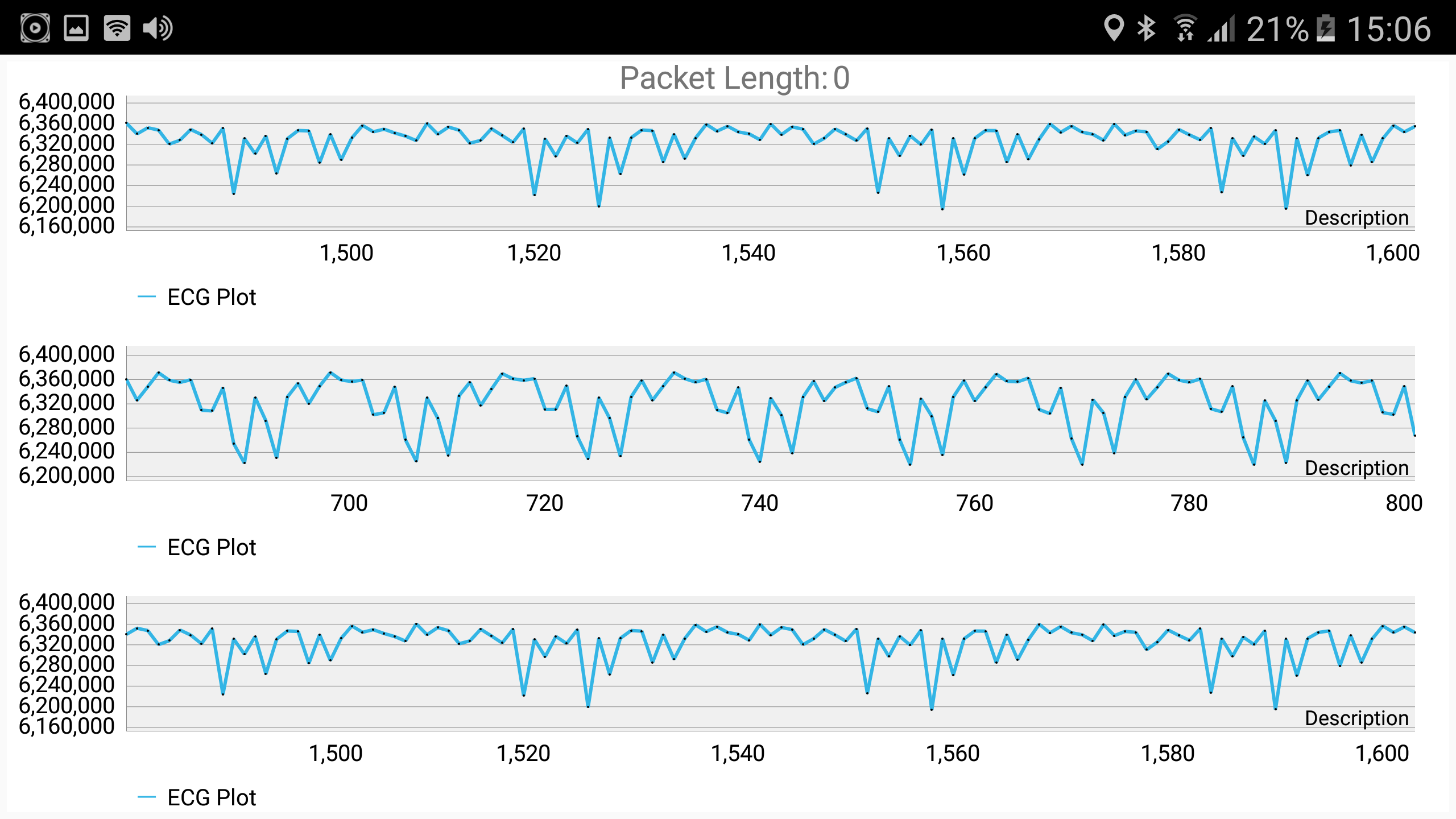
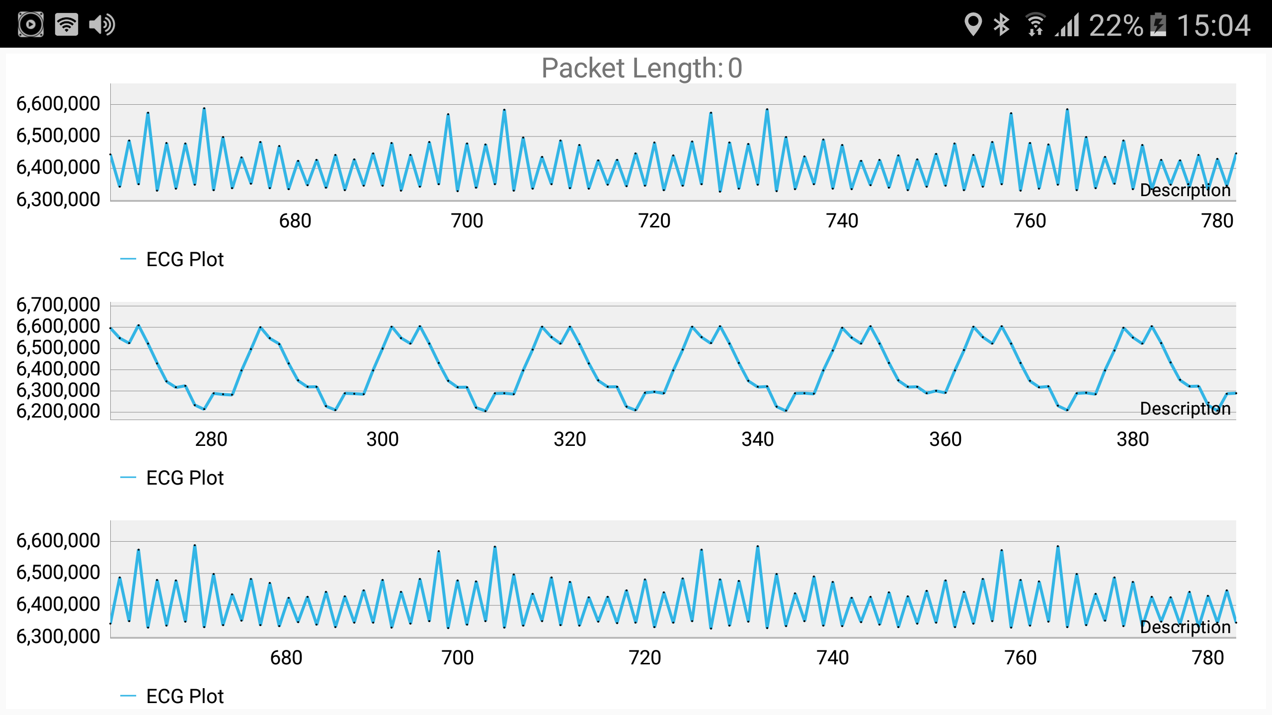
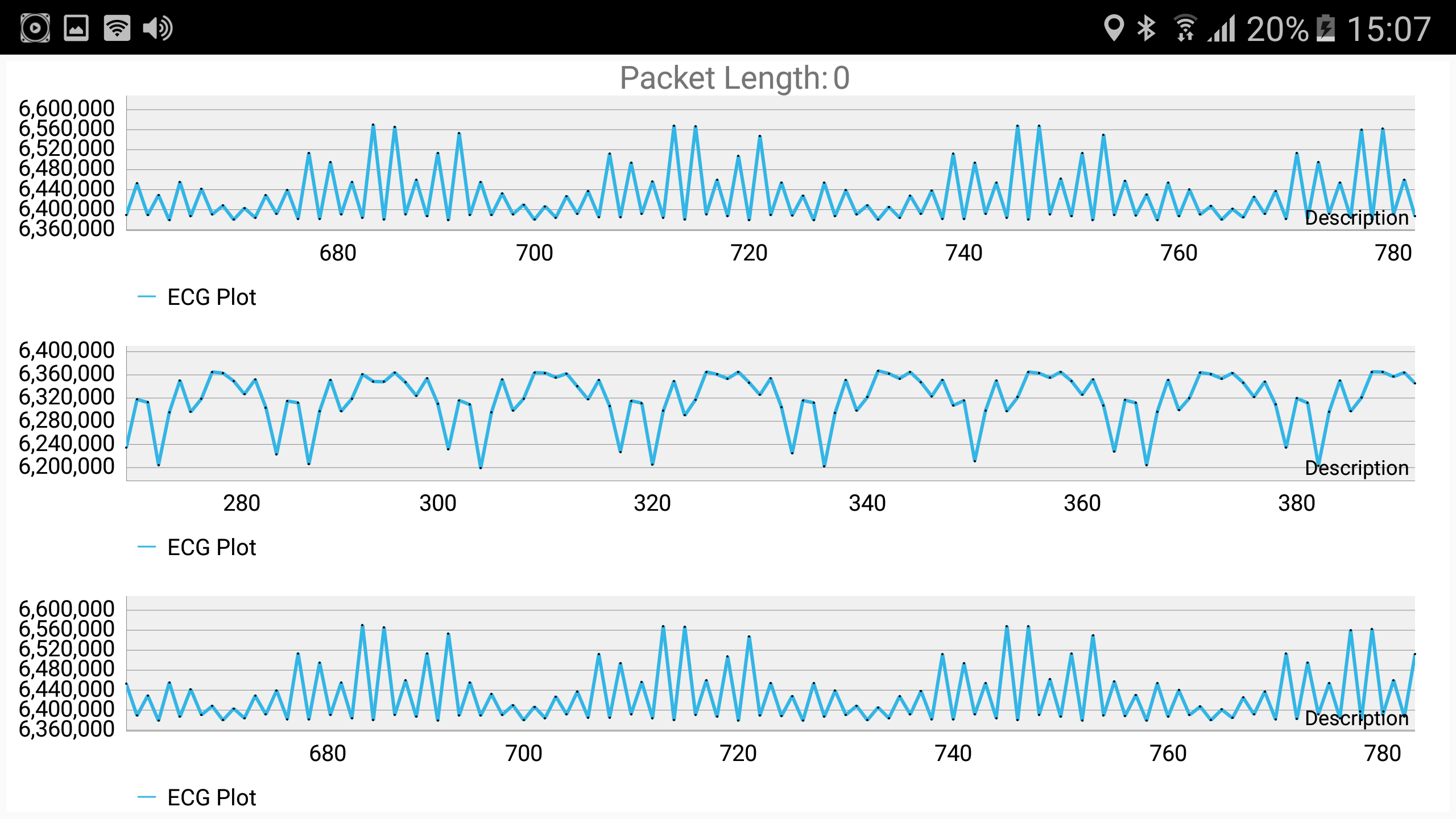
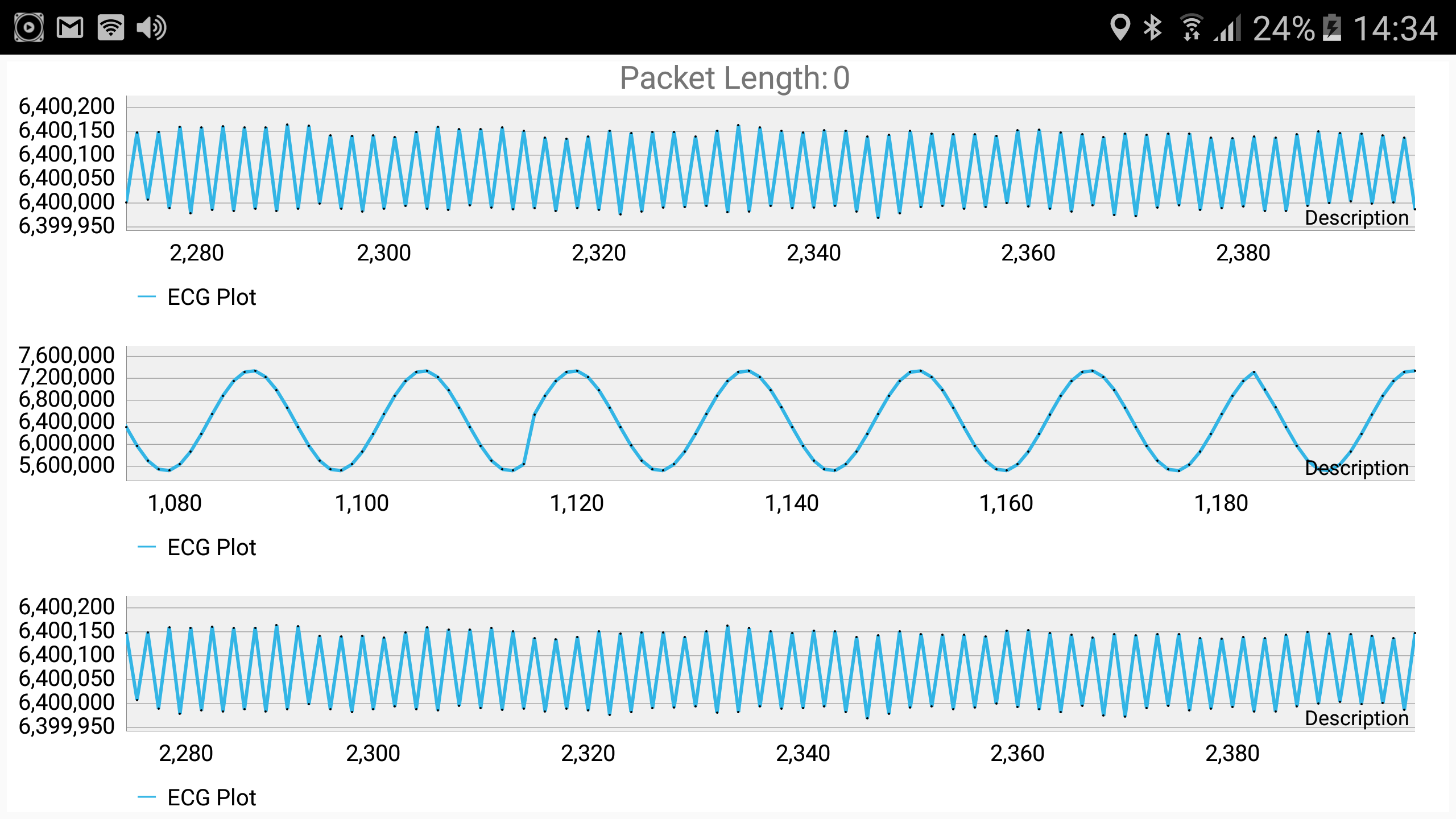
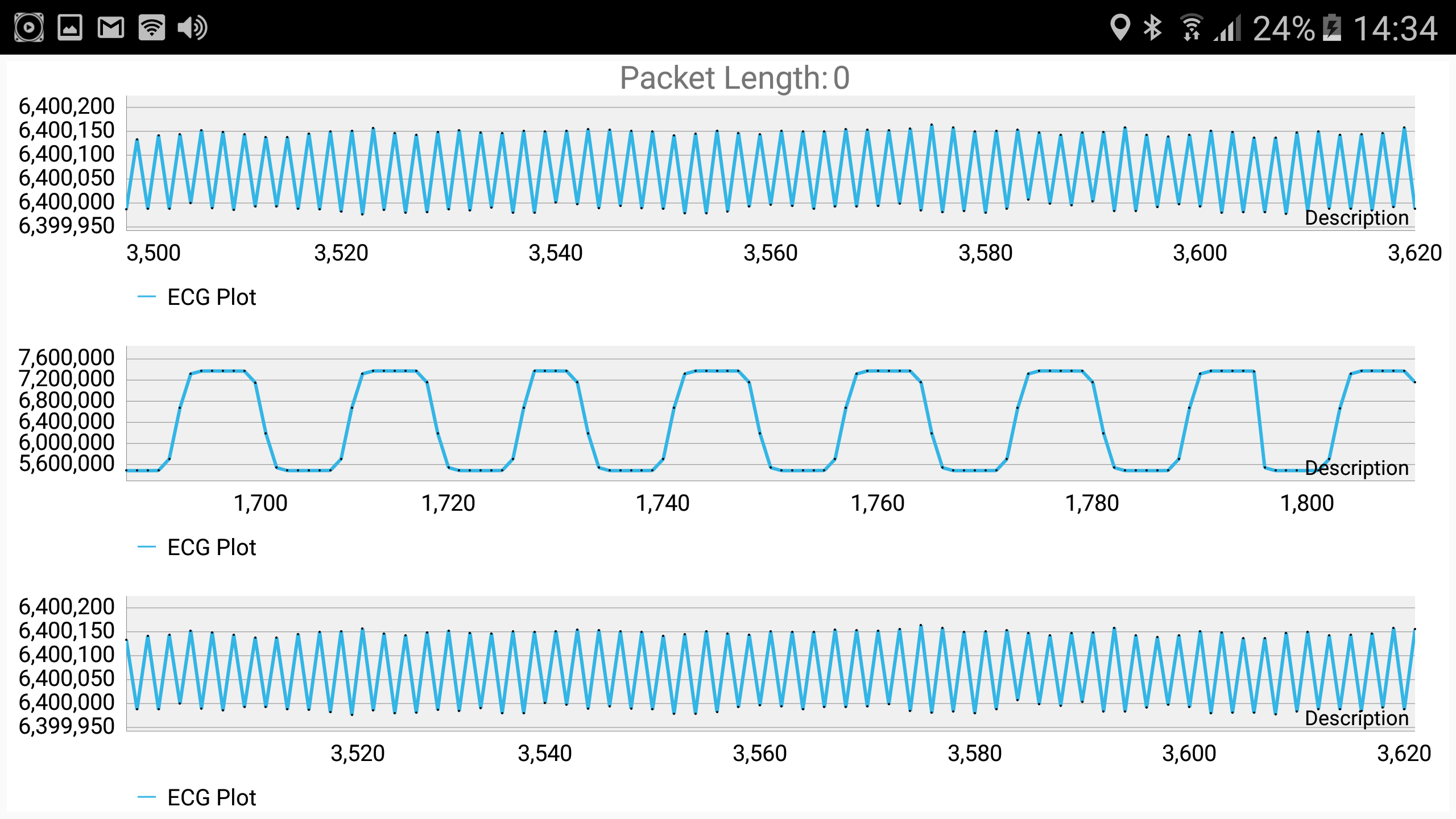
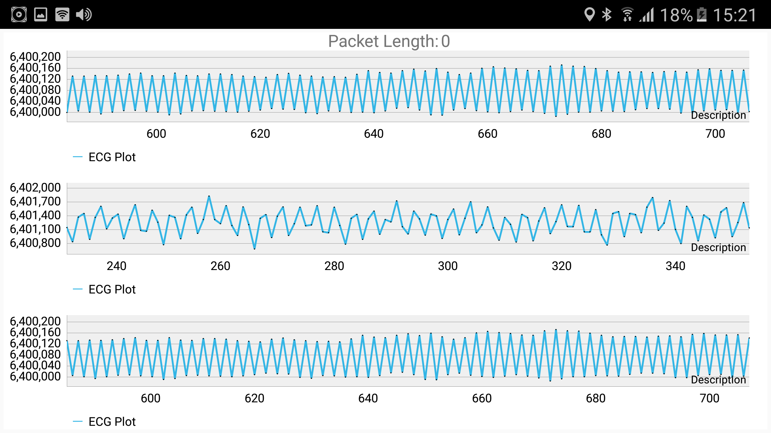
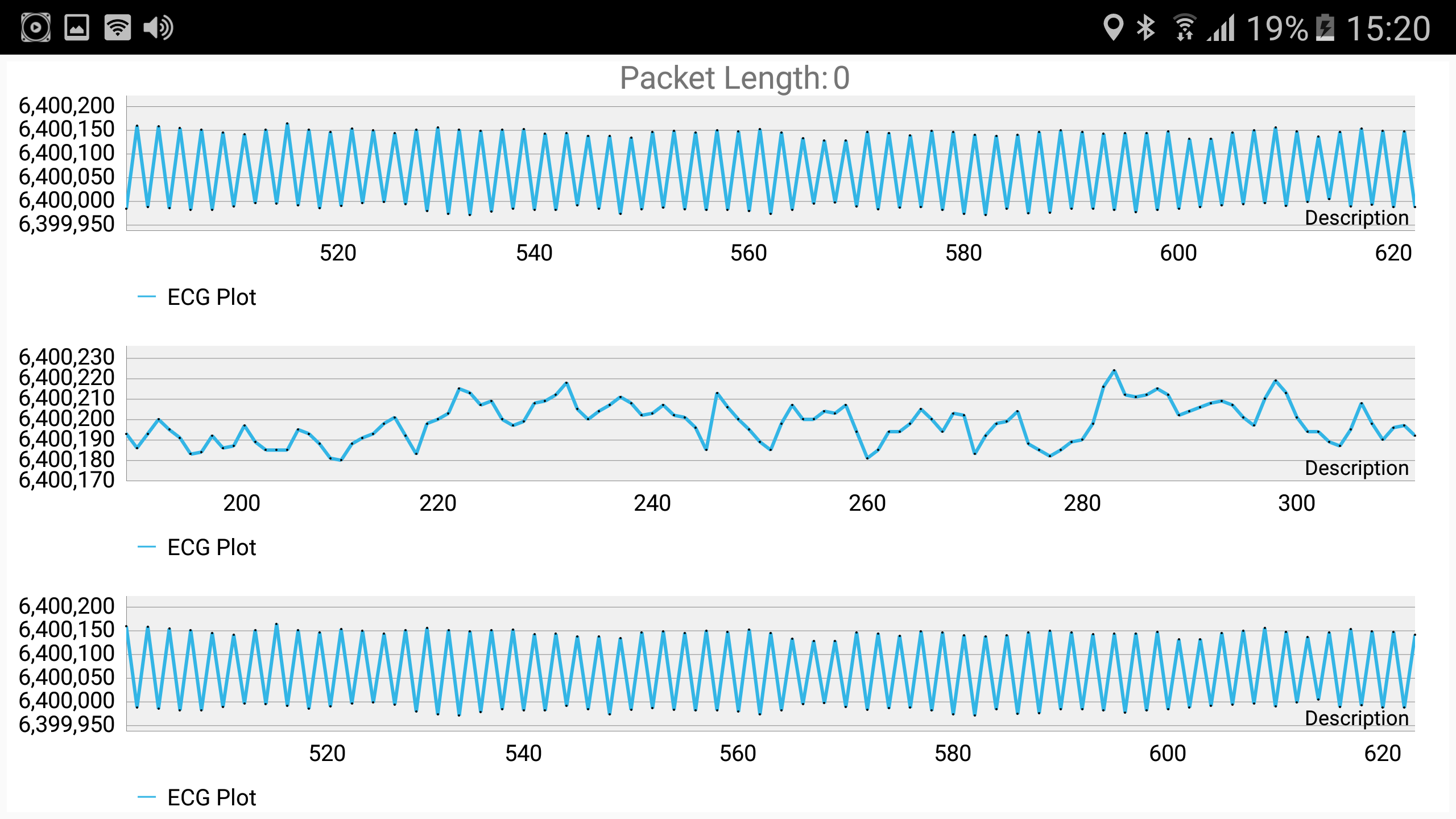
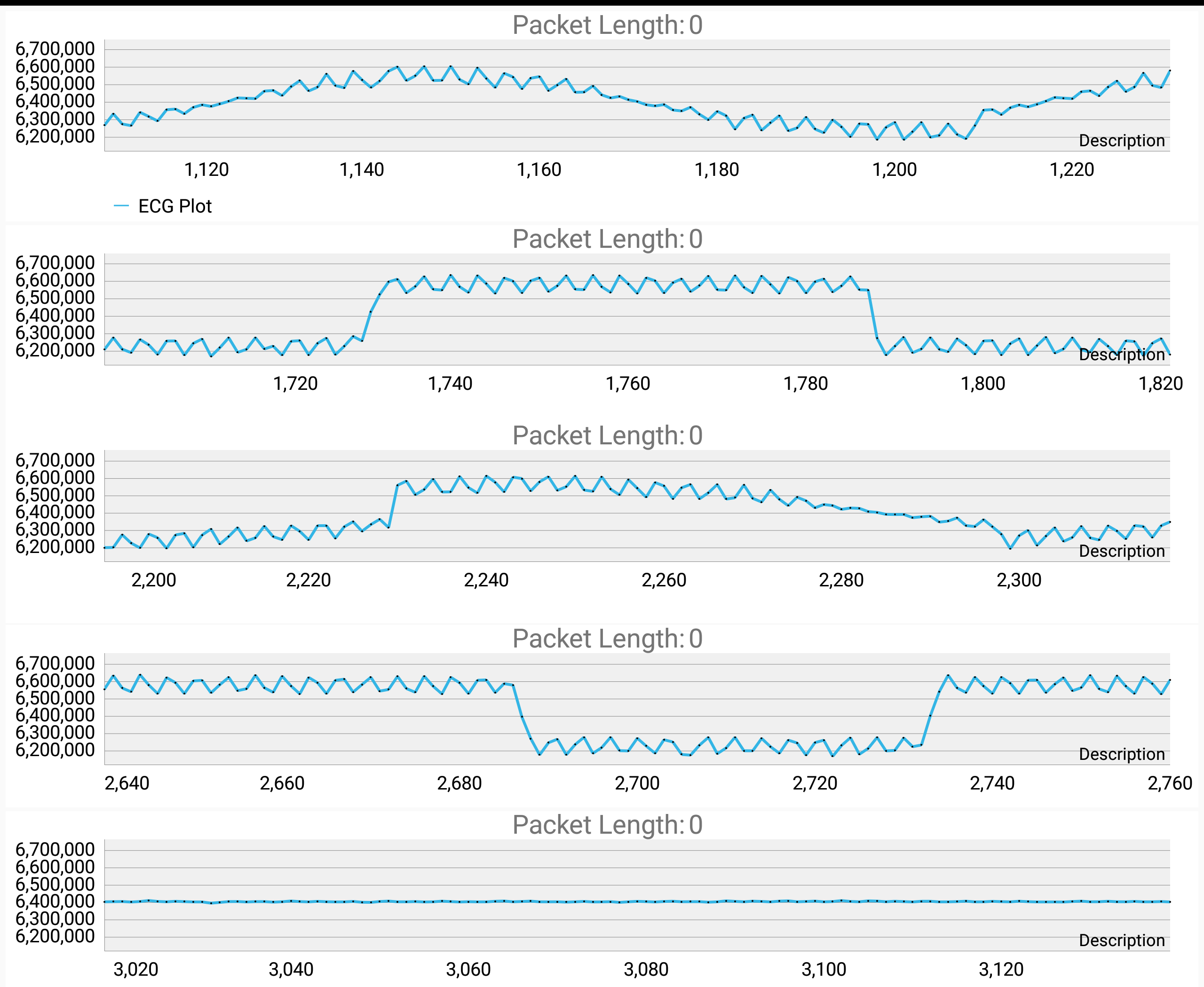
Frequency was set to either 1 Hz or 10 Hz at 200 mV. The shapes of the input in graphs below were always in this order: sine, square, ramp, pulse and noise. I have kept sampling rate in firmware at the default value.

I was wondering if the results below are normal? What is the cause of this noise and how may I filter it? Is this a hardware or a software issue? 

Thanks for help in advance.
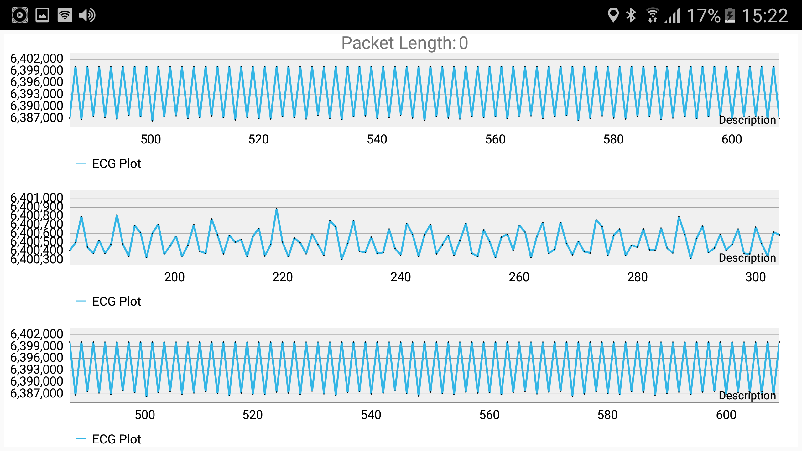
LL- LA channel1 1Hz

LL- LA channel1 10Hz

LL- LA channel2 10Hz
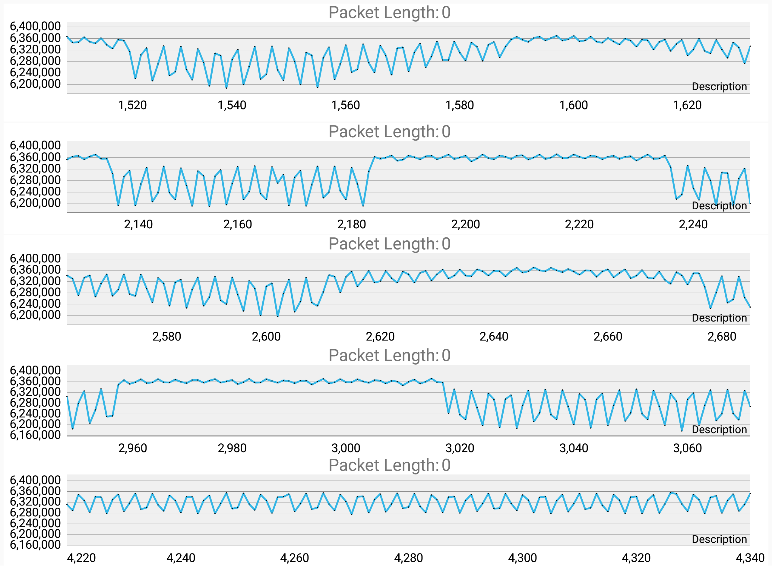
LL- V1 channel2 1Hz

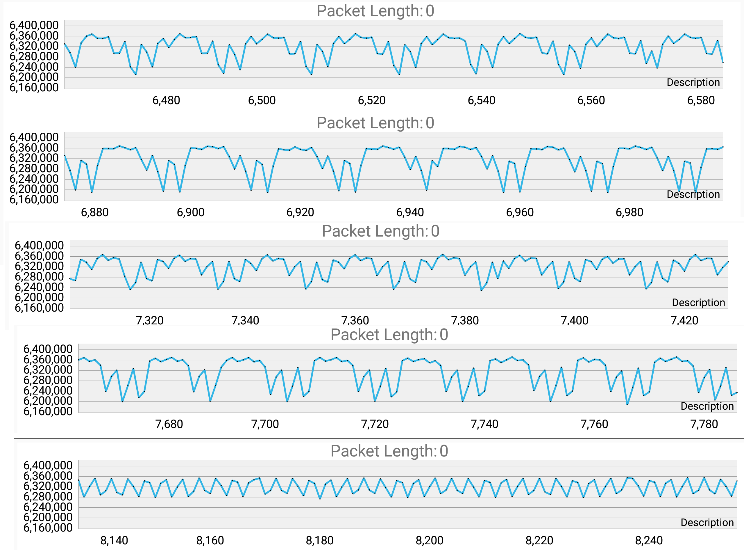
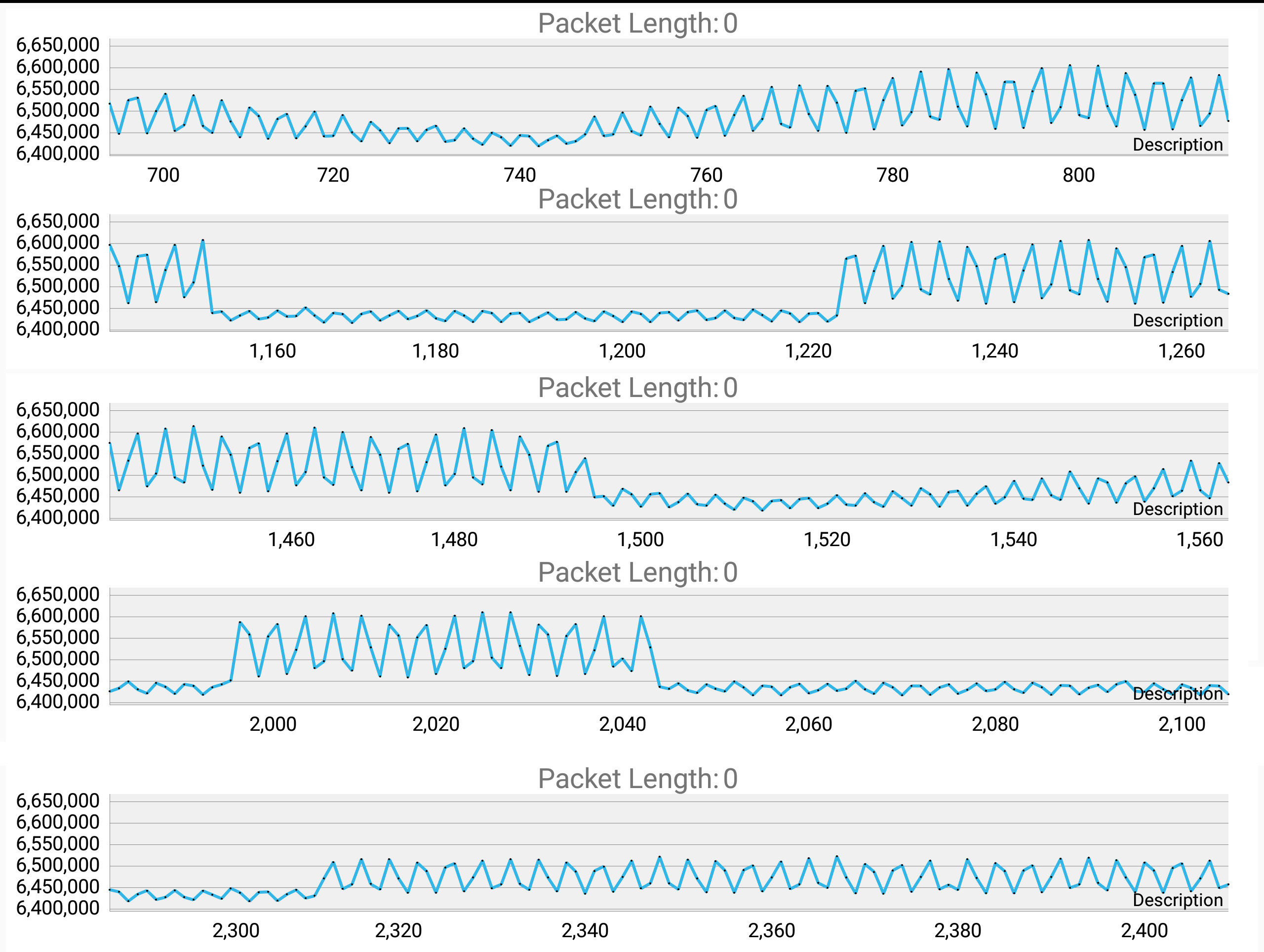
LL- V1 channel2 10Hz

LL- V1 channel3 1Hz

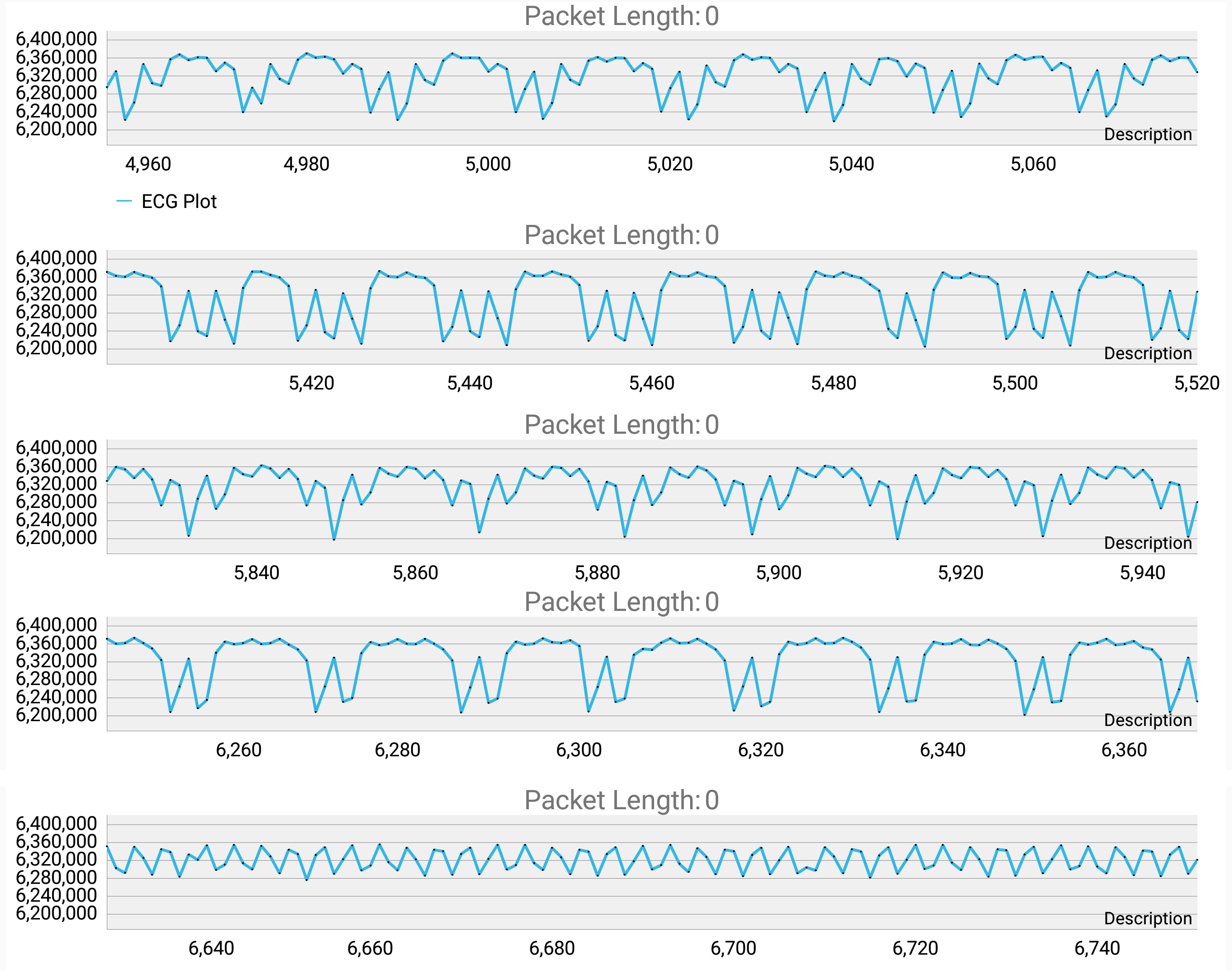
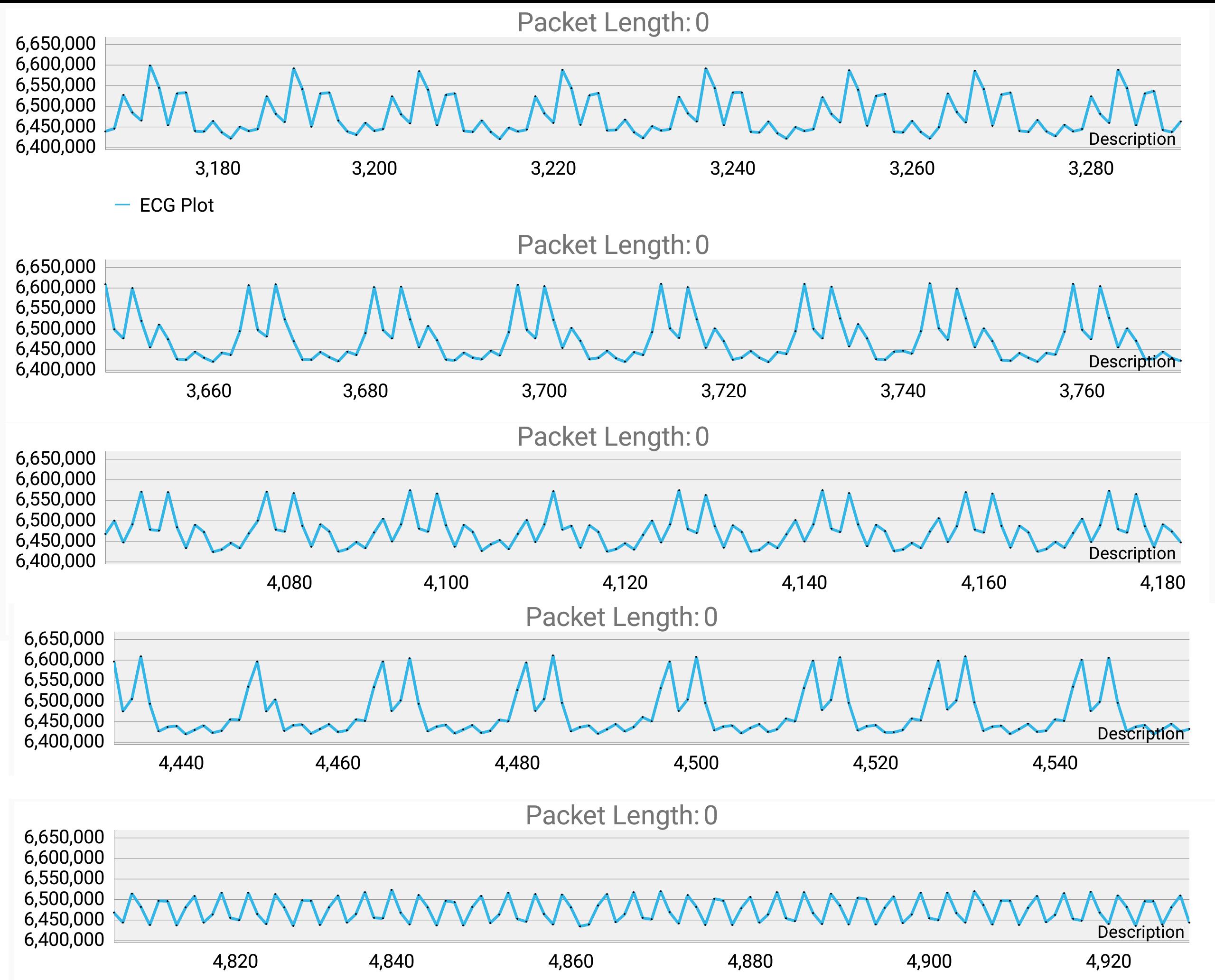
LL- V1 channel3 10Hz
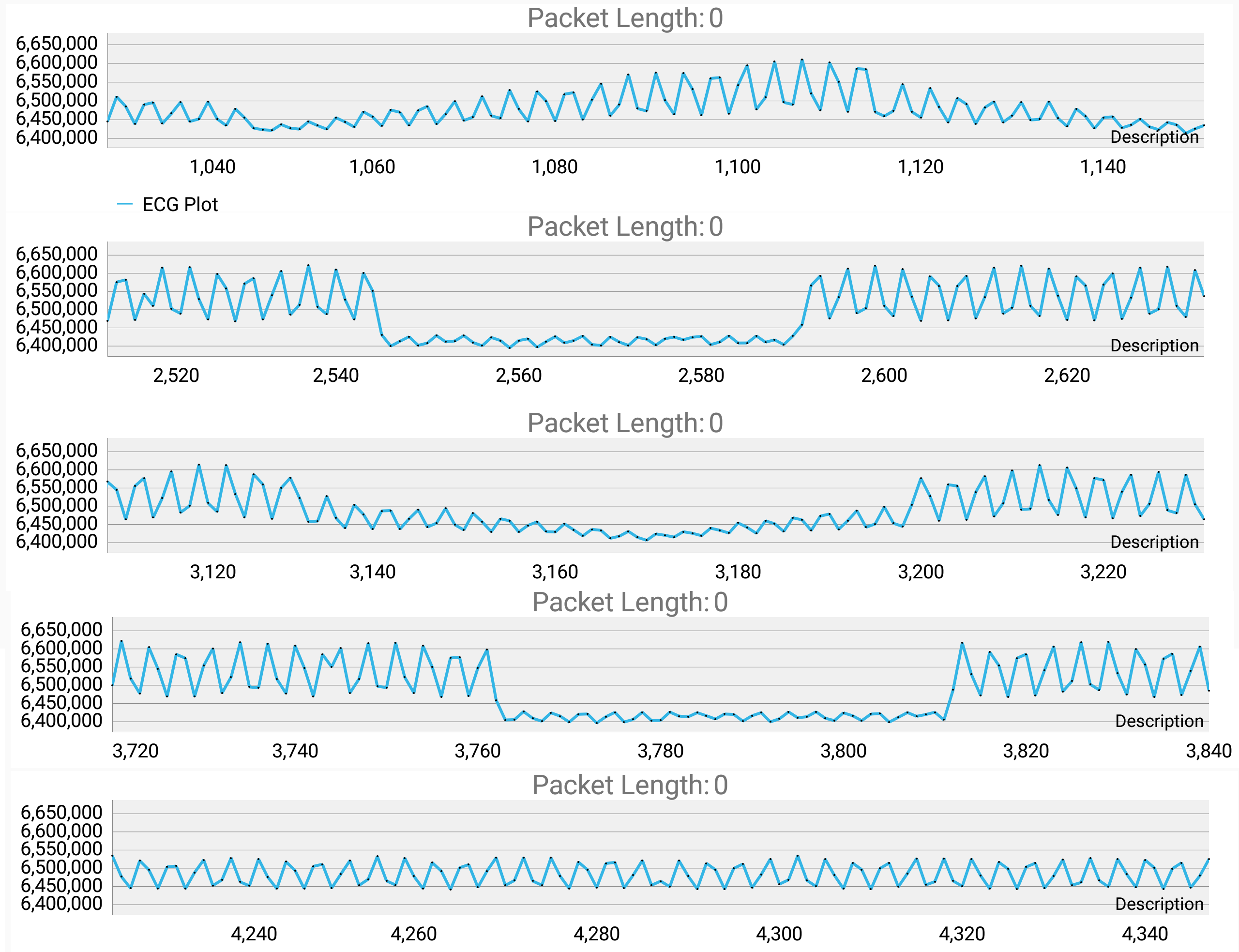
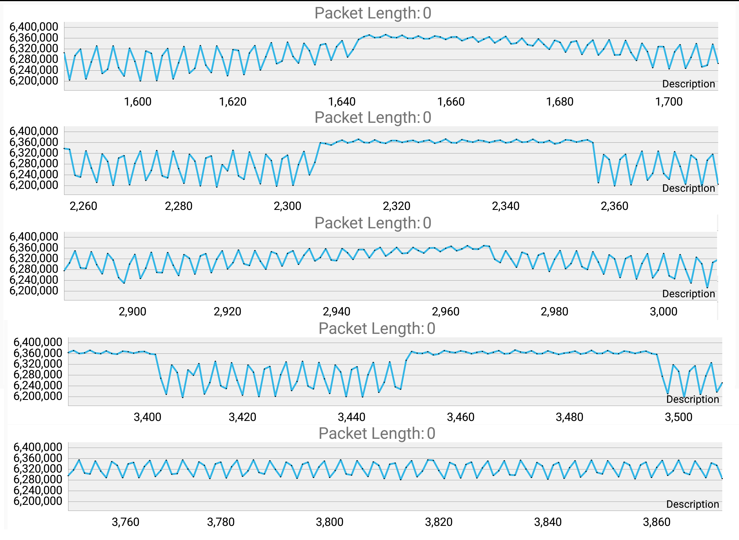
LL-RA channel1 1Hz

LL-RA channel1 10Hz

LL-RA channel2 1Hz

LL-RA channel2 10Hz

  • I have performed measurements again displaying 3 channels at once in the graphs. I have used 200 mV PP and 10 Hz using waveform function generator. Here are the combinations that yielded any graph changes. The questions remains the same though, so it would be really nice if someone could please answer them since I am really stuck here. Thank you.

    LL + LA

    LL + RA

    LL + V1

    LL-RL + LA (LL-RL means that I short circuited them)

    LL-RL + RA ramp

    LL-RL + RA sine

    LL-RL + RA square

    LL-RL + V1

    RL + LA

    RL + RA

    RL + V1

  • Hello,


    Just to make sure, please check that all wires and connectors are securely connected between your board and the generator. 

    When connecting the function generator directly to the inputs you need to make sure that your signal at the pins of the ADS1293 is less than the maximum

    allowed signal and within the CMVR. This is explained in section 8.3.5 of the datasheet. Also, make sure the RLD signal (a third wire) is connected to the

    function generator reference ground to create a ground reference between the ADS1293 EVM board and the function generator.  You will need to set the channel

    parameters (R2, and R3) properly to select the appropriate channel bandwidth, based on the frequency of the signal from the function generator.

    The ADS1293 INAs provide a gain of 3.5x  and you should be getting 1.4 V at the output for a 400mV input.  Check if you are converting the ADCout, the digital

    output value, correctly back to analog  value (see page 36 of ADS1293 datasheet).

    There is no filtering in the ADS1293 so that may be a problem. Some systems use analog high-pass filtering and a low resolution ADC. The ADS1293 has a

    DC coupled signal path and a high resolution ADC. The software behind the ADS1293 in the micro needs to remove the low frequency components.  You may need

    to write some code to implement a high-pass filter on the data from the ADS1293.

    Mike