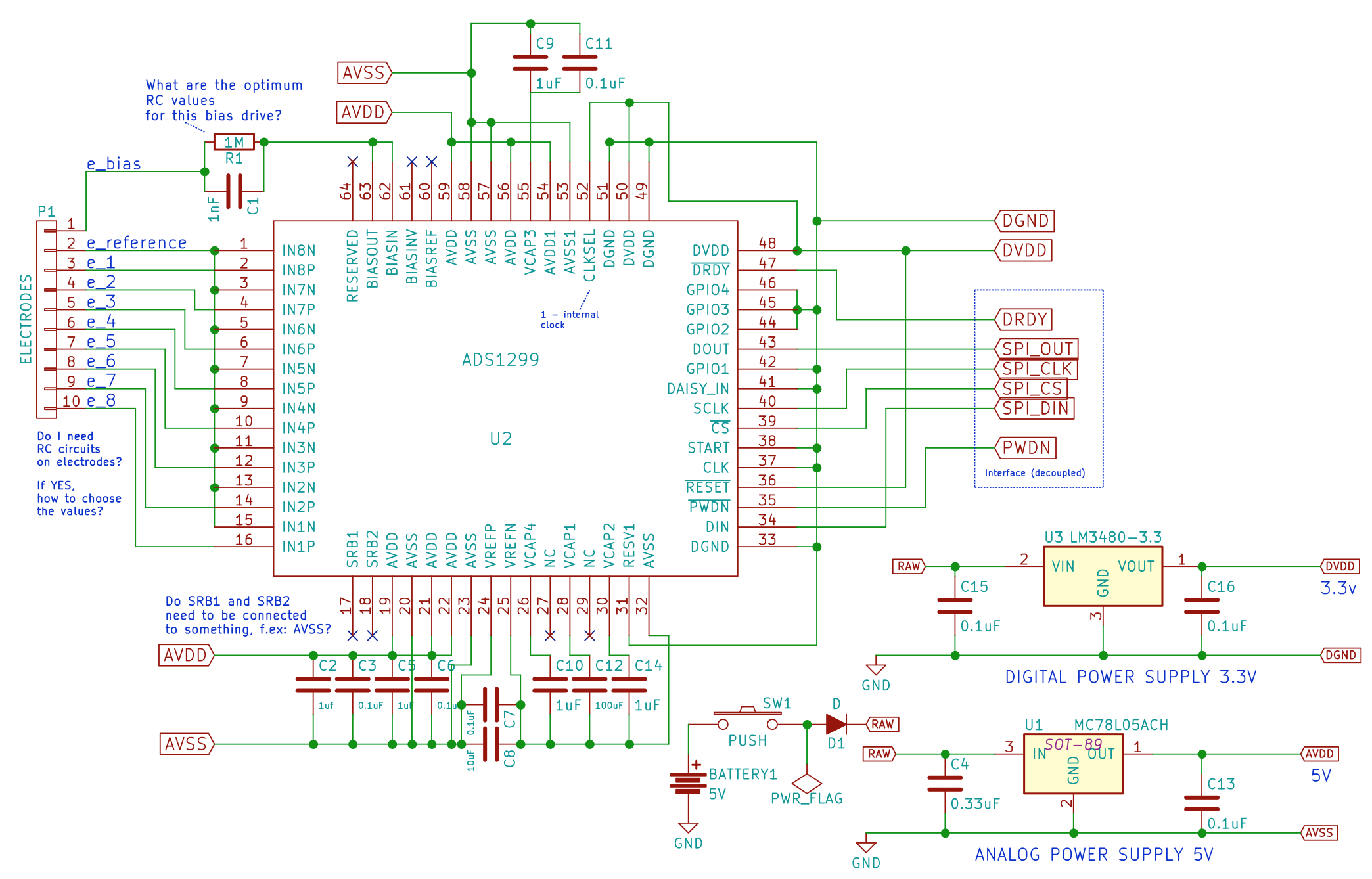
I am trying to design simplest schematics / PCB board for collecting EEG measurements using ADS1299.
This concept is based on ideas posted on this forum and inspired by Vojin Ilic:
Idea is:
-
The sensing electrodes are connected to positive inputs of all channels
-
The reference signal is fed to all negative inputs of the channels 1-8.
- Use only
BIAS_OUTpin of theADS1299without connection to theBIAS_INV. In this way you have open-loop amplifier in the feed-back loop of the first stage of the instrumentation amplifier. - Must use battery power supply, or if you use USB or some wall adapter, use isolation DC/DC converter for patient safety and for better CMRR performance.
The author's claim is:
"With this configuration, you will get CMRR of 143dB and will have great EEG recordings without using Notch filter of 50/60Hz."
Could someone validate this and review my schematics (disclaimer: I am more of a software developer and just a electronics hobbyist noob)?
Other questions I have:
1. Do I need C1 capacitor (RC circuit) and why or is resistor enough?
2. Do I need RC circuit on sensing electrodes in this setup? I see those sometimes but not sure what is the purpose?
3. I am using a unipolar voltage power supply. Is there a difference in using this compared to bipolar one?
Would appreciate any help. It is my 1st question on this forum, and as I said - just a beginner - so please be gentle ;-)


