This thread has been locked.

If you have a related question, please click the "Ask a related question" button in the top right corner. The newly created question will be automatically linked to this question.

2 Lead ECG circuit

Other Parts Discussed in Thread: ADS1292ECG-FE, ADS1292Hi,

I'm shimizu, TI Japan disty.

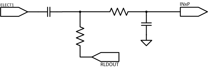
I am looking for a 2 electrode ECG schematic.
Could you give me the schematic of a 2 electrode ECG, please?

E-mail: m-shimizu@fujiele.co.jp

Best regards,
Shimizu
  • Hi Shimizu-san,

    Have you reviewed the schematic associated with the ADS1292?  It's located in the back of the ADS1292ECG-FE Users Guide.

  • Hi Shimizu-san,

    Typically, for 2 electrode ECG, the inputs to the ADS1292 will have to be AC-coupled and biased to mid-supply on the PCB. You can either use a resistor divider approach, or use a single high-impedance pull-up to the RLDOUT as shown below. The RLD amplifier can be configured to bias the non-inverting input of the amplifier to mid-supply using the device register settings.

    Best Regards,

  • Hi Ryan,

    Thank you for your support.

    Customer seen the below circuit.
    www.ti.com/.../tidr213.pdf

    Customer want to change from this circuit.
    Customer think below, Is it correct in case of two lead ECG circuit?

    In case of using RA and LA except RLD.
    1. RLD circuit (around U4 in above circuit) is removed.
    2. RA and LA is pulled up to Vref through 50Mohm resister.
    3. RG1 and RG2 connect to Vref

    Best regards,
    Shimizu