This thread has been locked.

If you have a related question, please click the "Ask a related question" button in the top right corner. The newly created question will be automatically linked to this question.

ADC12D1600RFRB Minimum Sampling Clock Frequency

Other Parts Discussed in Thread: ADC12D1600RF, ADC12D1600, ADC12D800RF, ADC12D500RF, ADC12D1600RB, WAVEVISION5, ADC10D1000

Hello,

I'm currently evaluating the ADC12D1600RF ADC in nonDES Mode using the ADC12D1600RFRB Evaluation Board and the WaveVision 5 Software. One of the performance parameters I'm evaluating is the chip's performance at a variety of sampling clock frequencies. I successfully reconfigured the Evaluation Board to use the external clock connection and I am able to collect samples at sampling clock frequencies of 420 MHz and higher.

However, I am NOT able to collect samples with sample clock frequencies lower than that. For example, when I set the external sampling clock frequency to 400 MHz, the WaveVision 5 software displays an error saying the board is unable to detect the sampling clock and the "DCLK_LOCKED" LED on the Evaluation Board is OFF.  If I increase the frequency to 420 MHz, the "DCLK_LOCKED" LED turns on and I am able to collect samples again. I also tried setting the Low-Frequency Select (LFS) register bit high to see if that helped but it didnt appear to make a difference.

The ADC12D1600RF data sheet says the ADC chip supports a Minimum Sampling Clock Frequency of 300 MHz (150 MHz with LFS set high) in nonDES mode so I *should* be able to use a sampling clock rate of 400 MHz. I checked the datasheet on the balun in the Sampling Clock path and its rated down to 400 MHz so it should be fine. Is there something else in the hardware design of the the ADC12D1600RFRB Eval Board that prevents reaching Sampling Clock rates of 400 MHz or lower? Or is there a problem with the Evaluation Software?

Thanks,

Bob

  • Hi Bob

    The lower clock frequency limitation is due to the FPGA firmware in the evaluation board. It has a limited frequency range and is optimized for the 1600 MHz clock rate. I will check to see if there is an alternate firmware that will enable lower frequency operation. The ADC12D1600RF datasheet does not have performance curves as a function of clock frequency, but the very similar ADC12D1600 datasheet does. There are a number of figures showing ENOB, SNR, THD and SFDR versus clock frequency, with the clock down to 250 MHz. The ADC12D1600RF performance trends will be very similar to that shown in these plots.

    If you have an application that needs samples rates that are always lower than 800 MHz clock rate you might also be interested in the ADC12D800RF and ADC12D500RF devices. These are pin compatible to the ADC12D1600RF, but have a lower maximum clock frequency.

    Best regards,

    Jim B

  • Hi Jim,

    Does this clock frequency limitation apply to the ADC12D1600RB EVM as well (2013 PCB REV B version)? If so, let us know if any alternate firmware to enable down to 250 MHz.

    Thanks,

    Phil
  • The same low frequency limits will apply for the ADC12D1600RB. I need to check to see how low it works and if any other firmware exists.

    Jim

  • Thanks Jim for checking on this! When should I expect a response for 1) How low it works and 2) If any other firmware exisits?

    Thanks,

    Phil
  • Hi Phil

    There may be a firmware that will work for the customer. Have him try the following steps:

    1. Navigate to C:\Program Files (x86)\National Semiconductor\WaveVision5\hardware\fpga_images
    2. Rename adc10d1000_xc4vlx25_adc12d1600rfrb.bit to adc10d1000_xc4vlx25_adc12d1600rfrb.bit.bak. This saves the original firmware for usage at higher clock rates
    3. Make a copy of adc10d1000_xc4vlx25_adc12d800rfrb2.bit
    4. Rename this new copy to adc10d1000_xc4vlx25_adc12d1600rfrb.bit (This is the actual file used by the ADC12D1600RFRB4).
    5. Launch WaveVision5
    6. Apply power to the ADC12D1600RFRB and connect the USB cable
    7. In WaveVision5 navigate to the Registers tab on the right and select the Config sub-tab
    8. Check the SDR box and click the Write Config Reg button
    9. Navigate to the Debug 0x00-5 sub-tab
    10. On the 0x0000 section click the Read button
    11. Change bit 8 from 0 to 1. This will set the LFS bit.
    12. Click the 0x0000 Write Button
    13. On the Settings sub-tab select External Clock

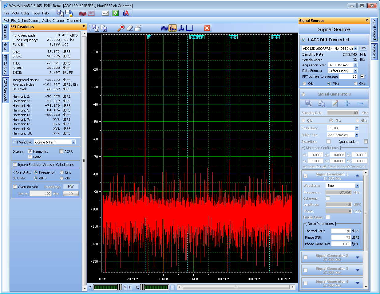
    With these settings I was able to sample with Fclk as low as 250 MHz.

    Here is the resulting capture at 250 MSPS in non-DES mode with 27.97 MHz Fin.

    Best regards,

    Jim B

  • This is great! I have shared this thread and will let you know if we need anything else.

    Feel free to mark this post answered for now if possible. I can't since I didn't ask the original question.

    Thanks for the support!

    Phil