


We are currently testing with the ADS1292R for both ECG and respiration, using the RA/LA without RL drive (Two-Terminal Measurement as per Figure 1 in the Ti document 'Respiration Rate Measurement Based on Impedance
Pneumography').
.
.
We've encountered an issue in which the respiration measurement can effectively invert, so we appear to measure a decrease in impedance as the chest cavity expands during inspiration. This change from inverted to non inverted measurement can occur during a single test or between tests. We understand (again from the above Ti doc) that this can occur when using a sine wave carrier and the phase shift is too large (>135 degrees), however we are using a square wave carrier (sine wave not possible on the ADS1292R). What conditions could cause signal inversion using a square wave carrier?
.
.
Similary, we suspect we may need to optimise the phase shift and frequency for our particular setup. We are currently using internal modulation and demodulation at a phase angle of 112.5 deg and modulation frequency of 32khz as recommended in the ADS1292R datasheet. Is there a procedure to follow to find the optimal settings for our sensors?
.
.
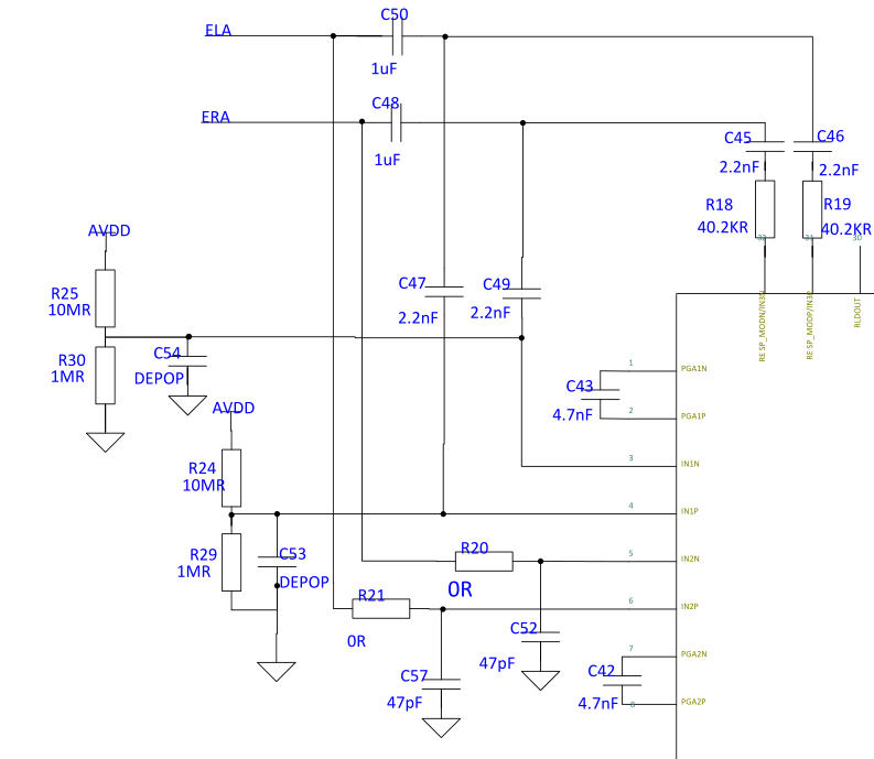
See attached our current RESP/ECG front end.
Registry Settings:
reg_config1 = 0x02; // continuous mode, sample at 500Hz
reg_config2 = 0xA0; // internal ref, VREF 2.42V
reg_loff = 0x11; // AC lead off (actually unused)
reg_ch1set = 0x00; // normal, gain = 6
reg_ch2set = 0x00; // normal, gain = 6
reg_rld = 0x00; // no RLD
reg_loff_sens = 0x00; // all disabled
reg_resp1 = 0xEA; // mod/demod on, 112.5 deg phase, all internal
reg_resp2 = 0x03; // 32KHz resp control freq, internal RLDREF

