Regarding the ADS1241, I would like to know if you can recommend a sequence for reading 4 channels by means of polling DRDY via SPI. I am not sure how to avoid reading corrupt data from the output register. Currently I do the following:
- read #DRDY bit, if 0:
- read result
- set gain for next conversion
- set mux
- sync
- dummy read to start modulator and reset DRDY
Possibly because of a problem in our application, the polling frequency may decrease in regular intervals, so periodically I get erroneous data.
At first I though this may relate to the possible situation where just after verifying DRDY==0, a conversion is finished and the output register updated, consequently corrupting the data read in the next step.
But now it almost seems that despite synching the modulator, the filter is actually causing the error (datasheet p. 10, fig. 2).
We're using a 4,915 MHz xtal, SPEED = 1, DR = 0.
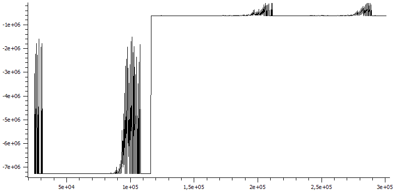
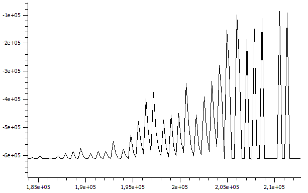
Although the application does not use the DRDY pin, I measured the low pulse-width and it increases in a linear fashion up to 20 ms (caused by polling too slowly). The data shows the same tendency, looks like the 10 percent error specified.
I may misunderstand the datasheet, but I was expecting no such error as I thought modulator, mux change and new conversion to be synchronized.
Swapping step 3 and 4, eliminating step 5, does not improve things.
Please let me know if the problem is likely caused by the filter settling and possibly how to avoid it. Thanks!