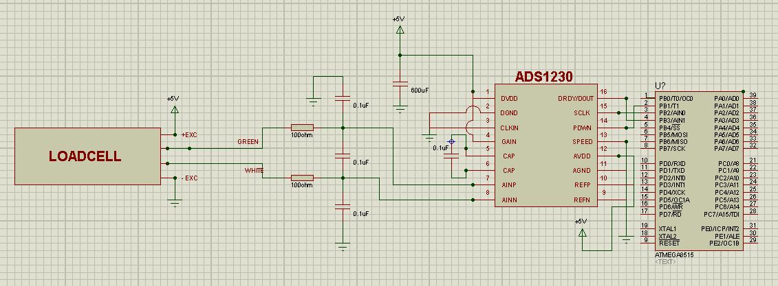
On Fig 33 of AD1230 data sheet the load cell is directly connected to the Pin No 7 and 8 of the IC. Is it recommended to connect a Series Resistor of 100 Ohms in between the Load cell and Pin Nos 7 and 8 respectively and also add a 0.1uF Poly Cap between 7 and 8 and another 2 Nos. to connect 7 to GND and 8 to GND. Kindly advise. We are facing problems and the ADS1230 data is latched in between during a periodic weighing scale measurement.. When we try to measure the voltage across Pin No.7 and 8 using Multimeter then the ADS1230 shows the normal voltage and is released from this latch. The latch generally occurs at 6 to 7 mV. The weighing scale is subjected to an increasing ramp of 2mV to 8mV periodically every 14sec. After 2 to 5 Hours we see that the ADS1230 output as read by the controller is latched up at 7 mV whereas the actual load on the loadcell is around 2mV. When we try to measure the ADS1230 goesback to 2mV. This is a board supplied with a LoadCell vendor and the circuit has three 0.1uF capacitors one between 7 and 8 and another between 7 and GND and also between 8 and GND. There is also a 100 Ohm resistor in between the load cell to ADS1230 on pins 7 and 8 respectively.

-
Ask a related question
What is a related question?A related question is a question created from another question. When the related question is created, it will be automatically linked to the original question.