Dear Sir/Madam
The setup is the DAC3484evm with the TSW1400evm. We would like to set it up, using only the internal 19.2MHz with CDC62005 excluding the primary clock input, so no need for an external clock. The goal is to reach low frequency, 2MHz. If you could show us any example in this range by showing the right calculation and configuration in both GUI’s, it is desirable. From there, we can change it to our exact wished frequency, once it is clear to us!
Briefly, what we have done so far,
Hardware,
Placed jumper4 on pin 2-3
Jumper5 on pin 1-2 (those jumpers, We have put them at all possible combinations)
Software,
installed all needed drivers for both as indicated in the guides, no problems at all.
DAC3484evm
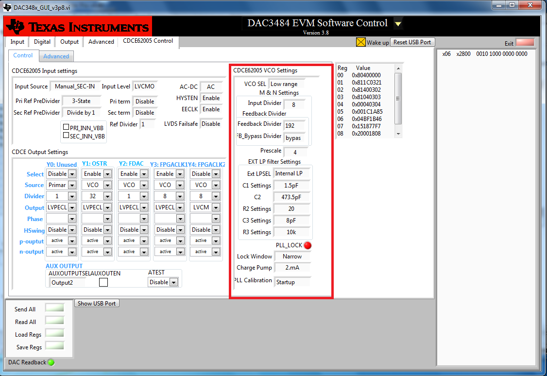
loaded from the Example folder, PLL configuration (DAC3484_FDAC614p4MHz_4xint_NCO_30MHz_QMCon_CDCE62005VCO)
from there I made some modification to the CDCE62005 (indicated in the picture in the attachment)
TSW1400
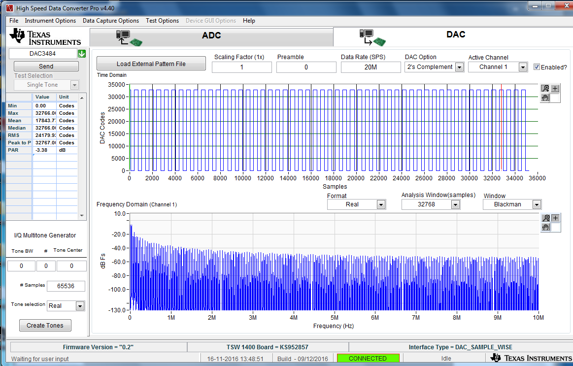
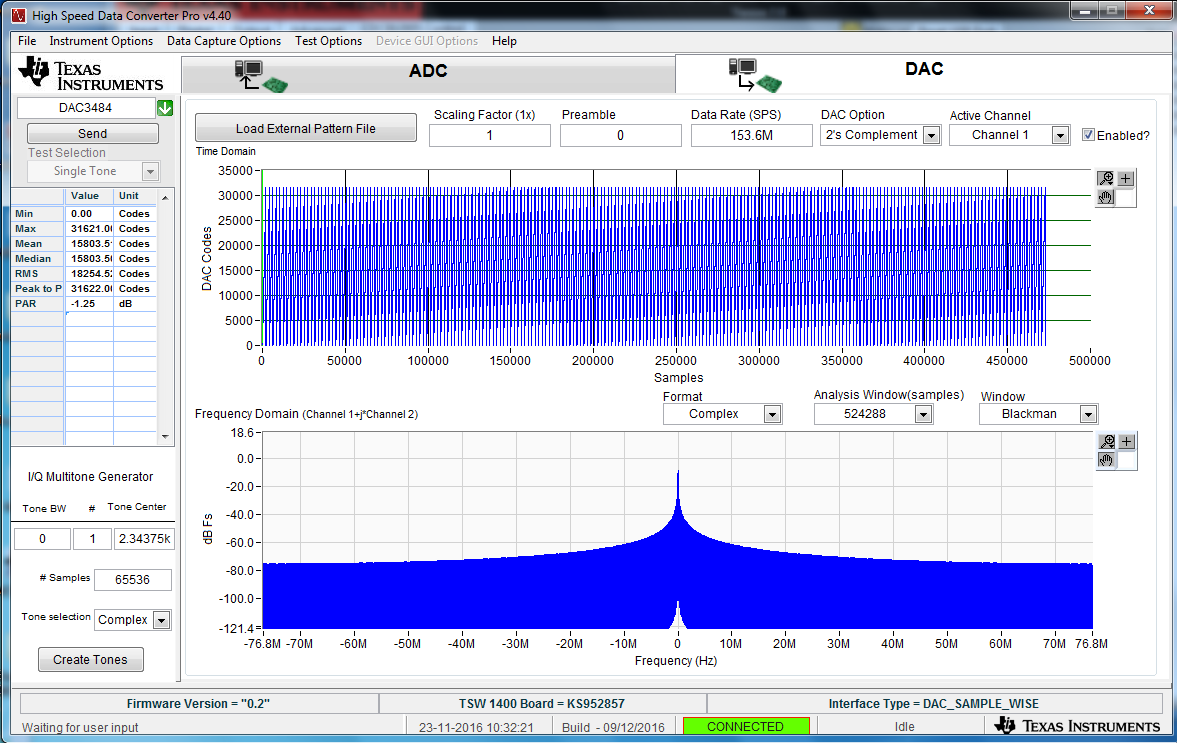
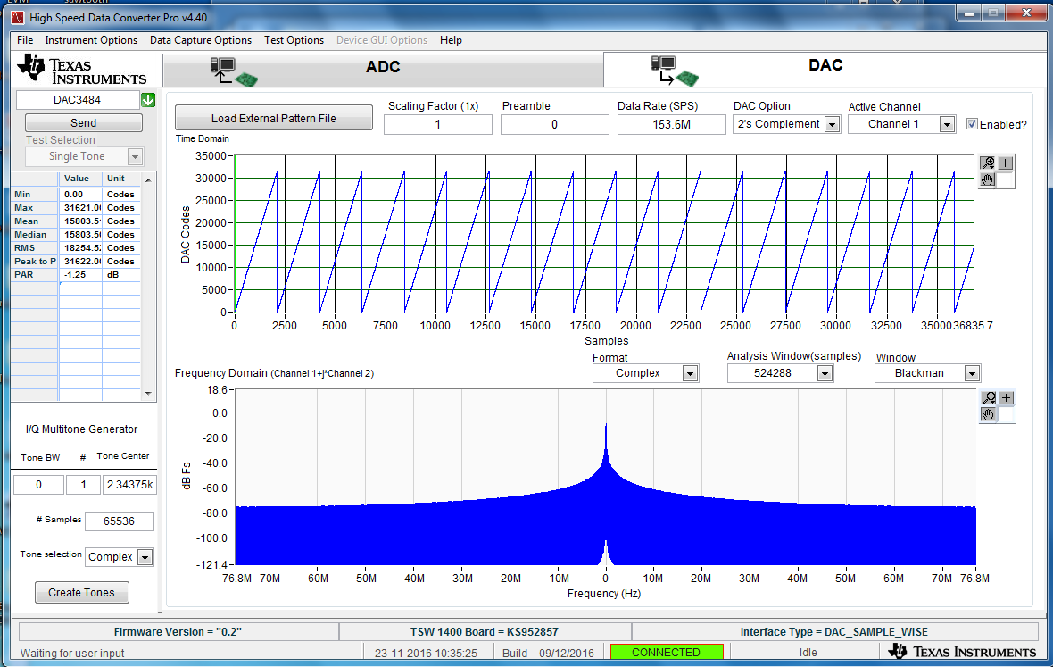
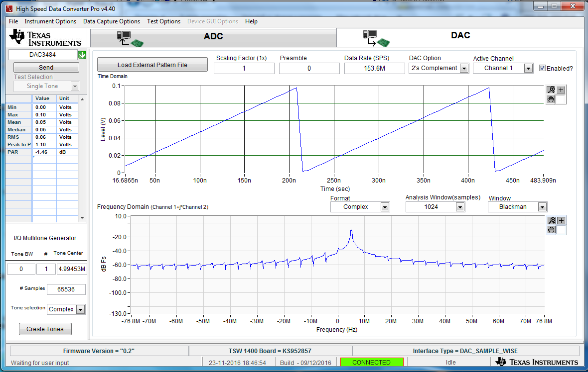
Loaded basic square wave. It showed in the GUI with no problems (see attachment).
From 20MHZ data rate (HSDC pro), the boards LEDs are not showing me that there is a problem with the clocking (LED1 from DAC3484evm and LED4 from TSW1400 )
The problem we don’t see the wished signal but rather random signal (see attachment) on the oscilloscope, which is directly connected from the DAC board channel 1 to the oscilloscope.
If any point is not clear regarding our question or an ambiguous setup, please contact us.
Kind regards,
Kamal


