This thread has been locked.

If you have a related question, please click the "Ask a related question" button in the top right corner. The newly created question will be automatically linked to this question.

ADS1192 channel 2 causes interference to channel 1

Other Parts Discussed in Thread: ADS1192, ADS1292, TL072

HI,

I am using ads1192 to acquire ECG and another pressure signal.

ECG was connected to channel 1 and the pressure signal was connected to channel 2. I read the ADS1192's data by a MCU and send them to a PC.

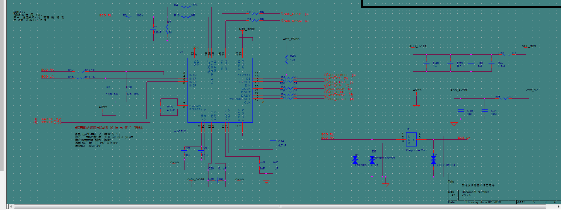
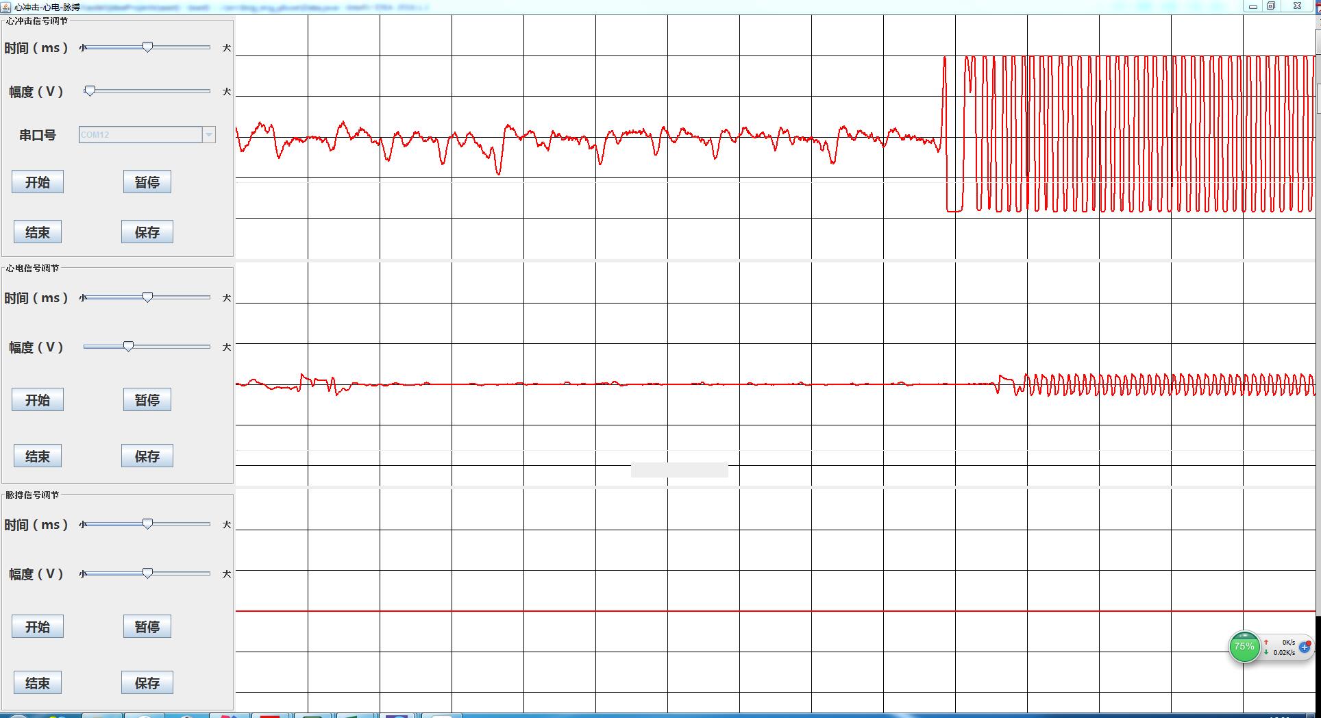
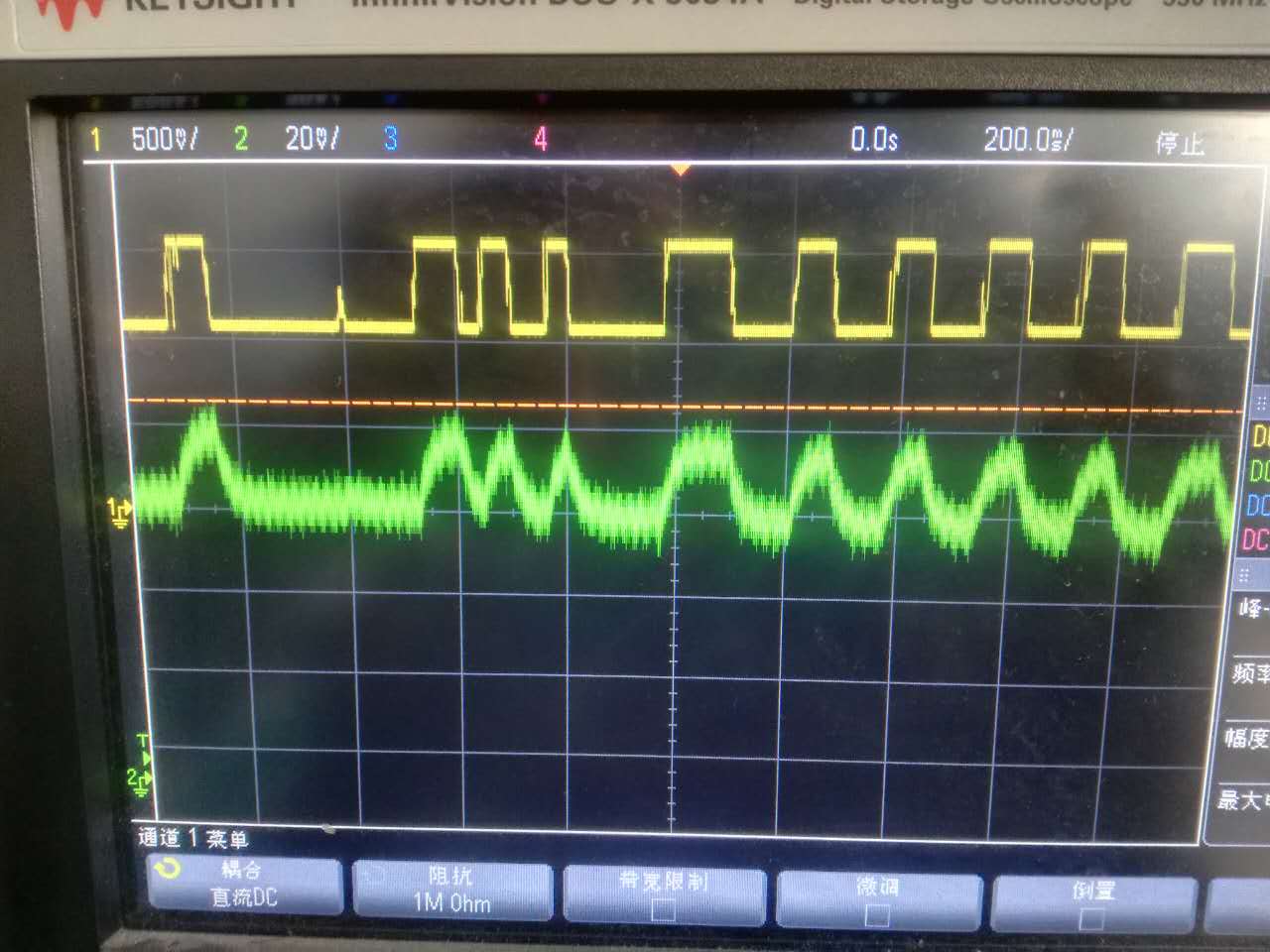
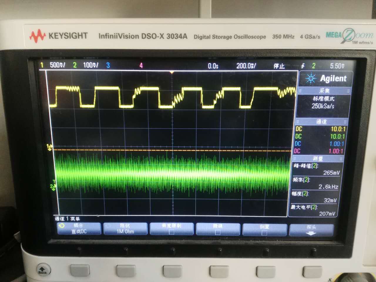
When  I only measure ECG, the signal is just correct. Howerver, Interference was occured when I connect the pressure signal to channel 2.

I don not konw why.

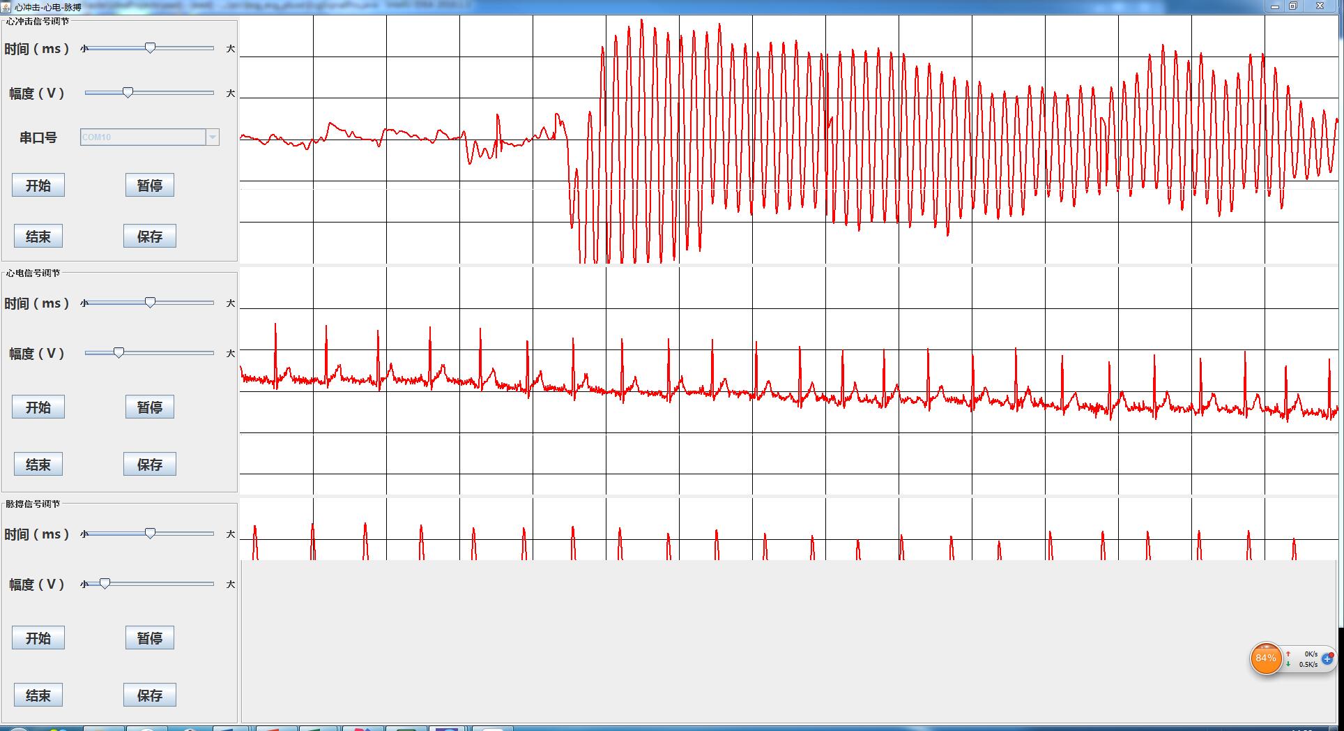
The pressure signal is single ended and its range is from -3 to +3V. ADS1192 is powered by 5V and ther reference voltage is chosen to be 4.2V.

The register is as follows.

ADS1292_START_DISABLE;//停止ADS1292转换
ADS1292_CS_DISABLE;//先禁能ADS1292片选
ADS1292_CS_ENABLE;//使能ADS1292片选
delay(10);//延时1秒

SPI_WriteByte(RESET);//发送复位指令对ADS1292进行复位
delay(3);//延时3毫秒

SPI_WriteByte(SDATAC);//发送停止连续读指令
delay(3);//延时3毫秒

//连续转换,500sps
writeRegister(0x41,0x02);//配置寄存器1位分布:连续/单次转换模式(bit7)、保留(0,bit3-6)、速率(500SPS)(bit0-2)
delay(3);//延时3毫秒
temp = ReadRegister(0x21);
//使能参考缓冲器,参考电压选择4V
writeRegister(0x42,0xb0);//0b1011 0000配置寄存器2位分布:保留(1)、脱落比较使能、参考电压缓冲器、2.4v/4vDA比较电位选择、内部时钟输出使能、测试信号开关、测试信号频率

//lead off detection
writeRegister(0x43,0x11);//配置寄存器3位分布:比较器阈值澹(分别在95%和5%)(bit7-5)、保留(1,bit4)、导联脱落电流幅度澹(6nA)、保留(0)、直流脱落检测

//0b0110 0000 增益12, channel 1
writeRegister(0x44,0x60);//通道1设置寄存器位分布:PD,GAIN2,GAIN1,GAIN0,MUXn3,MUXn2,MUXn1,MUXn0;正常工作模式,增益为12,正常电极输入

//0b0001 0000 增益1, channel 2
writeRegister(0x45,0x60);//通道2设置寄存器位分布:PD,GAIN2,GAIN1,GAIN0,0,MUXn2,MUXn1,MUXn0;正常工作模式,增益为12,正常电极输入

//通道二不需要右腿驱动
writeRegister(0x46,0x21);//右腿驱动设置寄存器分布:放大器工作速率?(bit7 6)、使能RLD缓冲器、RLD感应功能、通道2反相端RLD连接、通道2同相端RLD检测、通道1反相端RLD连接、通道1同相端RLD连接

//
writeRegister(0x47,0x00);//0、0、直流脱落检测流向(bit5 4)(在直流导联脱落检测中,ADS1292的8个通道中差分输入的同相端通过上拉电阻连接到AVCC(ADS1292模拟正电源),反相端通过下拉电阻连接到AVSS(ADS1292模拟负电源))、两通道的反、同相端脱落检测 ?
writeRegister(0x48,0x00);//0、时钟分分频(0:512kHz时钟4分频,1:2MHz时钟16分频)、0、RLD连接状态(只读)、两通道反、同相连接状态(只读)
writeRegister(0x49,0x02);//呼吸控制寄存器1分布:RESP_DEMOD_EN1ESP_MOD_ENESP_PH3、RESP_PH2、RESP_PH1、RESP_PH0、1、RESP_CTRL,通道1解调、调制电路使能,呼吸调制信号相位,呼吸调制时钟选择


writeRegister(0x4A,0x82);//calibration on, RLDREF is fed internally
writeRegister(0x4B,0x00);//GPIO配置寄存器:0、0、0、0、GPIOCTRL(2 1)、GPIODATA(2 1),GPIO引脚未使用

ADS1292_CS_DISABLE;//禁能ADS1292片选

  • Hi Xianwen,

    Can you share a description of the interference that you see on channel 2 of the ADS1192? A schematic of your circuit would be useful to review as well.
  • Hi, Tom

    Thank you for your help !

    The pressure signal is magnified and filterd by a series of operational amplifiers and then send to the chanel 2 of ads1192. When I pressed the sensor, the input of the channel 2 was saturated because of the amplification factor. At this time, the ECG on of channel 1 is disappeared, and the saturated signal on channel 2 was observed in the data of channel 1. 

    channel 2 is sigle ended and the saturated singal is from -3V to 3V.

    The schematic of ads1192 is as follows. The IN2N is now connected to GND , and IN2P is connected to the output of a amplifier (TL072, also from TI).

  • Hi Xianwen,

    The input voltage to the ADS1192 cannot go below AVSS. When you say that the SE input of the sensor can swing to -3V, is that the input voltage to CH2 when CH1 is also corrupted? If so, you will need to scale and level shift the input signal so that it swings from 0 to Vref.
  • Hi Tom,

    Thank you for your help!

    I plan to add add a ADC drive which can covert the single-end signal to diffrential signal. Dose the diff-signal also need to swing from 0 to Vref ? The datasheet said it can swing from -Vref to Vref. 

    Thanks.

    Xianwen

  • Hi Xianwen,

    If you go with a differential input, the +/-Vref input is fine as long as you do not drive any input signal below AVss - please take a look at Figures 16 and 17 on page 17 of the ADS1192 datasheet.
  • Hi Tom,

    Thank you! 

    I add a adc drive to convert the single-ended signa to deifferential signal. I measured the input of channel 2, the IN2N swing from 1.05V to 1.55V and the IN2P swing from 1.0V to 1.48V. The common mode voltage was set to 1.25V. The PGA gain for channel 2 was set to 1. The AVDD was set to 4V and the AVDD was set to 3.3V. The differential input met the requirement of ADS1192 acoording to the datasheet. 

    The interference is still there! When I pressed my sensor, the signal of channel 2 was saturated and the signal of channel 1 was collapsed. See the figure below. The upper signal is from channel 2 and the lower one is from channle 1.

  • Hi Xianwen Zhang,

    If the signal at the point ~2/3rds of the way through the upper signal is the point at which you pressed your sensor, the signal is bouncing back and forth between the two limits. If it's saturating both positive and negative, that indicates you either have a problem in your code or the input is switching back and forth (i.e. oscillating). Can you send a screen capture of the actual analog input to CH2? Another possibility is that you damaged the chip if you were driving the input to -3V previously.
  • Hi Tom,

    we tried it in other boards and they are same. I think that the ads1192s  might not be damaged in all boards. 

    I found that when I pressed the sensor the input of channle 1 also changed. But if I pluged in the ECG connector,  the interference disappeared. See the sample points we measured when the the channel 1 connected to the body.

    I measured the input of the channle 2 when I pressed the sensor. See the figure below.

    I also measured the input of IN2P(positive input of channle 2 ) and the input of IN1N(negtive input of channel 1) without the ECG connector plugged. see the figure below.(yellow one is the input of channel 2)

    When I plugged the ECG wires to channle 1, I repeated the measurement. See the figure below.(yeloow one is the input of channel 2)

    I do not know how the input of channel 2 affects the input of channel 1 and why it disappeared after the ECG wire was connected to channel 1.

    Thanks.

    Xianwen

  • Hi Xianwen,

    Thank you for the additional detail!  I did not realize that you had 'open inputs' on the the ECG channel.  Generally speaking, having open analog inputs is not the best situation to have while performing measurements - you can get some cross coupling in that situation.  If you can try a little experiment for me and use an external pullup on the ECG channel, then re-run your pressure sensor test and see if the signal still couples through, I'd appreciate that.    

  • Hi Tom

    I pulled up IN1P and IN1N to 3.3V, and the coupling disappeared. In open situation, it is still there. 

    So, the conclusion is that two channles of ads1192 will coupled if one channle is open ?

    Thank you!

    Xianwen

  • Yes, that can happen. I'm happy to hear that you've got it working now!