This thread has been locked.

If you have a related question, please click the "Ask a related question" button in the top right corner. The newly created question will be automatically linked to this question.

ADS8881 displaying codes despite active din

Other Parts Discussed in Thread: ADS8885, ADS8881

Hello,

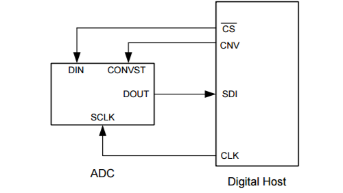
We're evaluating the ADS8881 on the ADS8885 EVM without the MMB0.  We've evaluated the device in both the four wire configuration and three wire configuration, and in both see unexpected output.

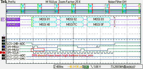
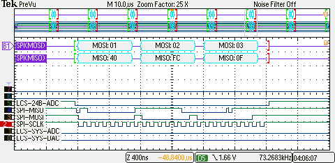
The four wire mode, pictured below, shows a MISO LSByte of 0x0F--the very lowest for this 18bit A/D should be 0x3F, correct? (please note, we aren't actually sending 1,2,and 3 on MOSI, it's more for debug purposes.)

I see the same behavior with 3-wire configuration:

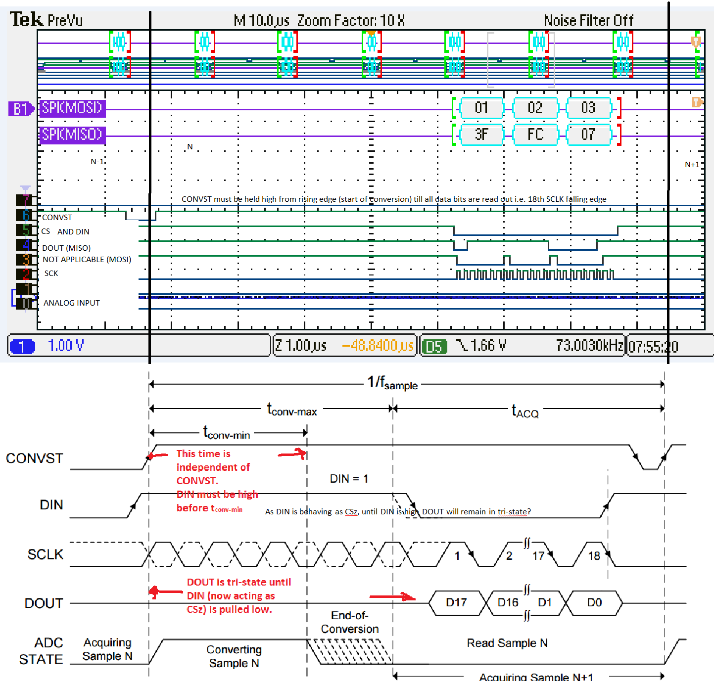
This other scope shot fits the datasheet description for four-wire operation exactly, with an extremely long conversion time, but the values are still strange.   In the above shot, CONVST is channel 6, and the large gap is a generous conversion time.

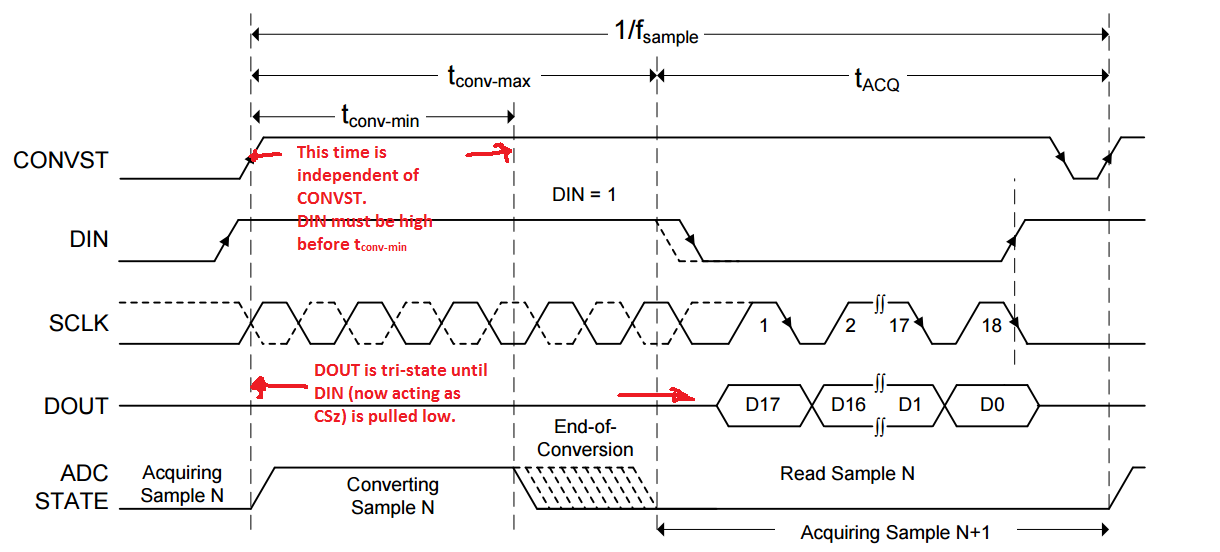
"In this interface option, DIN is controlled by the digital host and functions as CS. As shown in Figure 55, with DIN high, a CONVST rising edge selects CS mode, forces DOUT to 3-state, samples the input signal, and causes the device to enter a conversion phase. In this interface option, CONVST must be held at a high level from the start of the conversion until all data bits are read. Conversion is done with the internal clock and continues regardless of the state of DIN. As a result, DIN (functioning as CS) can be pulled low to select other devices on the board. However, DIN must be pulled high before the minimum conversion time (tconv-min) elapses and remains high until the maximum possible conversion time (tconv-max) elapses"

am I misinterpreting the datasheet?  Is Din tristate only for the conversion phase regardless of CONVST?  Should the second scope capture give the proper readout?  Probably missing something glaringly obvious here, thank you for your help!

  • Hi Aaron,

    If I understood your question correctly, you want to know if DIN should be pulled high synchronous to CONVST or before tconv-min.

    Please refer to the image below,

    1) DIN must be high before tconv-min. It does not depend on how long CONVST was high. Please see image below.

    2) CONVST must be held high from rising edge (start of conversion) till all data bits are read out i.e. 18th SCLK falling edge.

    3) As DIN is behaving as CSz, until DIN is high DOUT will remain in tri-state. In your frame, if you expect the last 6 bits, to be 1s, DIN must be high. Also, DIN is intermittently going high after every 8 clocks when SCLK is toggling this will cause the DOUT to tri-state.

    4) Only between CONVST rising edge and tconv-min, DIN can be pulled low. It must be high between tconv-min and tconv_max.

    High precision ADCs require buffered reference and ADS8881 does not have an internal reference buffer. We recommend using REF60xx family of references which include a voltage reference and a reference driver. You could refer to this EVM for information regarding REF60xx driving ADS8881.

    Regards,
    Rahul

  • Hi Rahul, thanks for the response.  I apologize for not clearly stating my question--I'd probably need to explain the analog signals a bit better.  Vdd is 3V, Vref is 2.5V from a buffered ref3xxx, and the analog input is approximately 2.5V, so the expected codes are FF FF XX, X being unknowns from noise (but higher than 3F because MISO seems pulled high if not driven). 

    I also wanted to clarify the hardware setup. This is the ADS8885EVM with the ADS8881 placed on it. Din and CS are the same signal, applied to the EVM jumpers.  We decided to look exclusively at 4-wire, so the screen capture taken at 4:06:07 is not what I'm referring to below (sorry about the confusion!). Referencing the original images, the connections are listed below:

    EVM Connections:

    J2-1        LCS-24B-ADC (signal 5 on screen cap)

    J2-3        SPI_SCLK (signal 2 on screen cap)

    J2-13      SPI_MISO (signal 4 on screen cap)

    J2-17      CNVT (signal 6 on screen cap)

      From your explanation, I was a bit confused on point 3, as it conflicts with what I saw on the datasheet Figure 55--the datasheet tristates on the rising edge and comes from tristate on falling edge from what I saw on the figure below.  I've included a "marked up" screen capture, please excuse my poor MSPAINT edits.

    From the above "setup", MOSI is not connected. It's strictly for scope debug purposes.

    I hope this clarifies things, is there something obvious I'm missing?