This thread has been locked.

If you have a related question, please click the "Ask a related question" button in the top right corner. The newly created question will be automatically linked to this question.

IDAC settling time while reading 4 sets resistors using ADS1262EVM

Other Parts Discussed in Thread: ADS1262

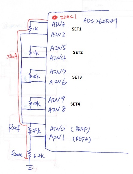
I use TI28335 + ADS1262EVM (serial/power interface connected) , and try to read the values of 4 sets resistors (1k,1k, 10k,10 respectively)

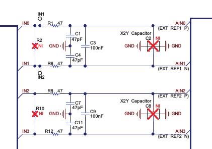
the circuit:

I use DRDY pins and interrupt routine to deal with the condition that the converted data is ready

use IDAC1 = 50 uA, and switch IDAC source among AIN3, AIN5, AIN7, AIN9 after each reading in ISR.

My question is the IDAC current source switch need additional time to settle down?  how long?

If I initialize ADS126x with longest DELAY time 8.8ms, the readback resistor value is correct.

but if I use shorter delay time than 8.8ms, the resistor value is not correct..

any hint??


I initialize the ads1262 with the following parameters

        set_adc_START(0);
	ADS126xReadRegister(ID, ADS126x_NUM_REG, AdcRegData, TARGET_ADC1);				//Read ALL registers

	WriteRegData = (AdcRegData[MODE0] & ~DELAY_MASK & ~RUNMODE) | DELAY_8800us;		//MODE0
	ADS126xWriteRegister(MODE0, 1, &WriteRegData, TARGET_ADC1);						//Configure Delay time

	WriteRegData = (AdcRegData[MODE1] & ~FILTER_MASK) | FILTER_SINC4;				//MODE2
	ADS126xWriteRegister(MODE1, 1, &WriteRegData, TARGET_ADC1);						//Configure Digital Filter

	WriteRegData = (AdcRegData[MODE2]  & ~DR_MASK) | DR_7200_SPS;					//MODE2
	ADS126xWriteRegister(MODE2, 1, &WriteRegData, TARGET_ADC1);						//Configure ADC1 data rate


	WriteRegData = MUXP_AIN3 | MUXN_AIN2;
	ADS126xWriteRegister(INPMUX, 1, &WriteRegData, TARGET_ADC1);					//Configure INPMUX

	WriteRegData = MUX2_NO_CONM | MUX1_AIN3;										//IDACMUX (IDAC1MUX = AIN3)
	ADS126xWriteRegister(IDACMUX, 1, &WriteRegData, TARGET_ADC1);					//Configure ADC1 data rate

	WriteRegData = MAG2_OFF | MAG1_50uA;											//IDACMAG (IDAC1MAG = 50 uA)
	ADS126xWriteRegister(IDACMAG, 1, &WriteRegData, TARGET_ADC1);					//Configure ADC1 data rate

	g_curSetting_ADC1 = THERMISTOR_SET_1;


	WriteRegData = RMUXP_AIN0 | RMUXN_AIN1;											//REFMUX (REFP = AIN0, REFN = AIN1)
	ADS126xWriteRegister(REFMUX, 1, &WriteRegData, TARGET_ADC1);					//Configure ADC1 data rate

	ADS126xReadRegister(ID, ADS126x_NUM_REG, AdcRegData, TARGET_ADC1);				//Read ALL registers Check Written Values

Interrupt routine:

set_adc_CS(0);
    ADS126xXferByte(RDATA1);                        //Send RDATA1 command

    for(i = 0; i < 6; ++i)
        ADC_Bytes[i] = ADS126xXferByte(0);

    set_adc_CS(1);
    if (ADC_Bytes[0] & ADC1_NEW) {					//ADC1 Data New?
		ADC_Data_Only = ((long)ADC_Bytes[1] << 24) |		//Data MSB
						((long)ADC_Bytes[2] << 16) |
						((long)ADC_Bytes[3] <<  8) |
						((long)ADC_Bytes[4] <<  0);		//Data LSB

       	unsigned char mag = MAG1_50uA;

        //switch to next set of resistor
 	ADS126xSendStopCommand(TARGET_ADC1);

	ADS126xWriteRegister(IDACMAG, 1, 0, TARGET_ADC1);							//OFF IDAC

	WriteRegData = MUXP_AIN5 | MUXN_AIN4;
	ADS126xWriteRegister(INPMUX, 1, &WriteRegData, TARGET_ADC1);						//Configure INPMUX

	WriteRegData_2 = MUX2_NO_CONM | MUX1_AIN5;							//IDACMUX (IDAC1MUX = AIN3)
	ADS126xWriteRegister(IDACMUX, 1, &WriteRegData_2, TARGET_ADC1);					//Configure ADC1 data rate
        
        
        ADS126xWriteRegister(IDACMAG, 1, &mag, TARGET_ADC1);						//IDAC1 50 uA

 	ADS126xSendStopCommand(TARGET_ADC1);         //start again after configuration
}

  • Hi Ivan,

    Do you have any filter capacitors on the inputs and reference pins?

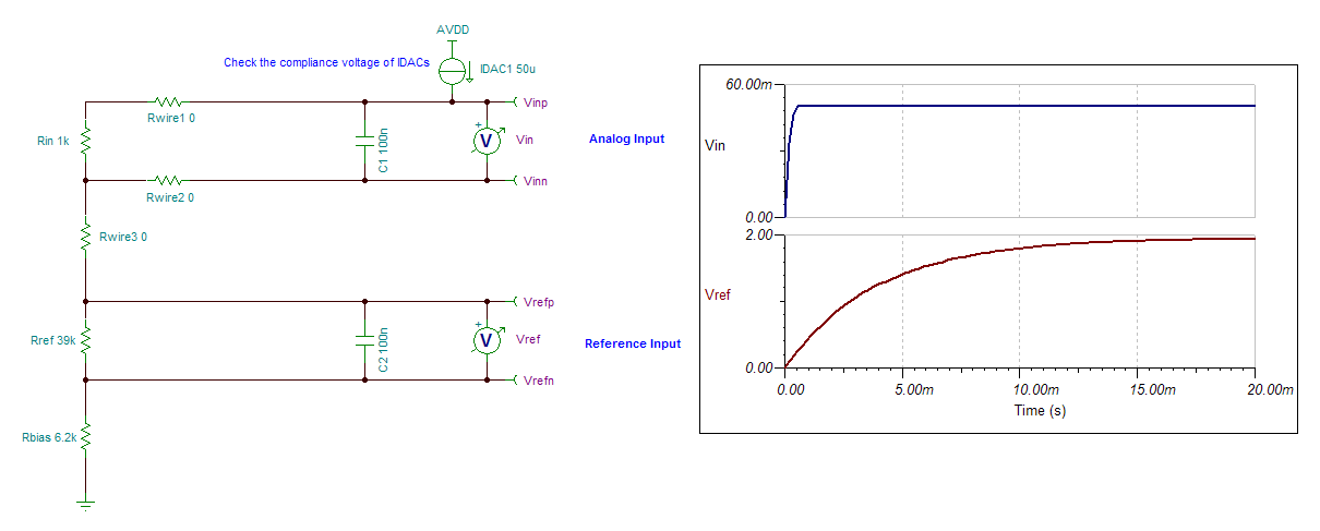
    The IDAC current source settling time is likely going to very negligible. You're probably seeing the settling time of the external "RC" components. The following TINA simulation circuit shows the likely settling behavior: 

    IDAC Settling.TSC

    The reference input will require the most time to settle due to the very large resistor used to generate the reference voltage. In the above simulation, I happened to see a similar settling time for the reference that matches what you're seeing (8.8 ms).

    You might consider either decreasing the reference resistor value or by externally buffering the reference voltage, in order to reduce the required settling time.


    Let me know if that helps!

    Best Regards,
    Chris

  • Thanks. It is really related to the RC filters.
    But due to application limit, i cannot change the scale of relative resistors. (consider the temperature range of thermistor)
    now, i just remove the capacitor of the input on ADS1262 EVM (100nf). after doing that, the result looks okay.
    What i need to do is to make a trade-off between noise filtering and response time..

    I try to adjust the value of RC filter
    any advice?

  • Hi Ivan,

    Buffering the reference input would probably have the most dramatic effect on the settling time, as this changes the RC time constant for the reference capacitor charging (the output impedance of the buffer would be much smaller than 39kOhm and so the settling would be much faster). However, the downside to this approach would be the added cost, as well as possible performance degradation from the buffer's offset, offset drift, and noise.

    Alternatively, if you just want to tweak the "R" and "C" values, I would make the reference resistor as small as possible (allowing for your required input range) and the reference capacitor as large as possible (to filter out reference noise and still providing an acceptable settling time).

    What is an acceptable settling time in your application and what is your targeted accuracy?
    Keep in mind that that capacitor settling requires LN(2^N) time constants, where N is the number of bits. Therefore, for a capacitor to settle to a 20-bit level (i.e. the error is on the order of 1 LSB at 20-bits resolution), requires LN(2^20) = 13.8 time constants.

    A couple other things to consider:

    • Reference noise shows up directly in the ADC output, so a smaller reference capacitor may slightly increase the noise seen in the conversion result. However, the ADC's digital filter will typically provide more noise filtering than the external "RC" filter. Therefore, if you use a slower data rate you may not see much, if any, effect on the noise when reducing the value of the reference capacitor.

    • If the IDAC current source is always enabled then consecutive conversions should settle a little faster, since the reference capacitor will retain much of it's charge. However, if this reference capacitor only retains 90% of it's charge, it will still require 11.5 time constants (out of the 13.8 time constants mentioned earlier) to settle back to a 20-bit level.

    • Another possible implementation would be to take advantage of the two IDACs in the ADS1262. You could create two different resistors strings and alternate your measurements between these resistors strings. IDAC2 would charge your second resistor string while you were measuring the first resistor string with IDAC1. Then during your next channel measurement you would switch IDAC1 channels to start charging the first resistor string again. This could speed up measurements a bit by doing these operations in parallel but it would also reduce your channel count slightly since you would need 2 reference inputs for this configuration.


    Best Regards,
    Chris

  • What you mentioned really helps us a lot. Thanks. 

    But I dont  really understand what you mention:

    Christopher Hall said:

    ...

    Buffering the reference input would probably have the most dramatic effect on the settling time, as this changes the RC time constant for the reference capacitor charging (the output impedance of the buffer would be much smaller than 39kOhm and so the settling would be much faster). However, the downside to this approach would be the added cost, as well as possible performance degradation from the buffer's offset, offset drift, and noise.

    ......

    ......

    How to buffer the reference input? Could you draw a brief circuit?

    thanks

    regards, 

                  Ivan

  • Hi Ivan,

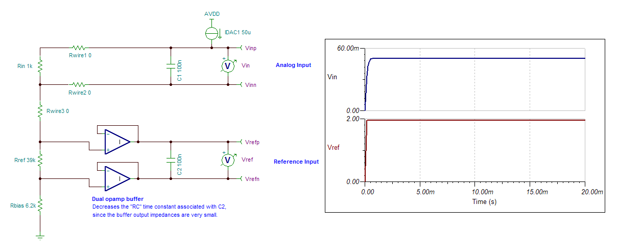
    No problem, this is what I was thinking for buffering the input:

    Notice that C2 is now buffered/separated from Rref, which previously created a large RC time constant. Adding these buffers allows C2 to charge up much faster, as shown in the graph on the right.

    ASIDE:

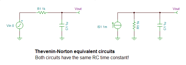
    Keep in mind that even though Rref is in parallel with C2, it still forms an RC time constant since this is the Norton equivalent circuit to the typical voltage driven circuit. I had to remind myself of this relationship when I first looked at your circuit...


    Best Regards,
    Chris

  • Christopher Hall said:

    ....

    Notice that C2 is now buffered/separated from Rref, which previously created a large RC time constant. Adding these buffers allows C2 to charge up much faster, as shown in the graph on the right.

    ...

    add ADS1262EVM circuit (AIN0 &  AIN1 for REFP & REFN)

    R1 & R6 & C3 in original circuit are designed for noise filtering (low pass filter)

    if I add dual-op to buffer the ref voltage, noise filtering does not work anymore?

    if it does not work, I simply remove the C3..

    thanks

    ivan 

  • Hi Ivan,

    In order to take advantage of the buffer and decrease the settling time of the circuit, you wouldn't want to place a capacitor before the buffer, since this capacitor would continue to slow down the settling.

    However, it would be okay to place a capacitor after the buffer to provide the noise filtering!

    NOTE: Adding a buffer would be a trade-off in performance here...the settling time would be significantly improved, but the buffer's noise and offset would add to the ADC's noise and gain error. Therefore, I'd probably only use a buffer in this circuit if I absolutely needed the faster settling time. Otherwise, I would try the other options (mentioned above) first!

    Best Regards,
    Chris

  • Hi Chris,

                  One more question. Your earlier explanation.

    Christopher Hall said:

    What is an acceptable settling time in your application and what is your targeted accuracy?
    Keep in mind that that capacitor settling requires LN(2^N) time constants, where N is the number of bits. Therefore, for a capacitor to settle to a 20-bit level (i.e. the error is on the order of 1 LSB at 20-bits resolution), requires LN(2^20) = 13.8 time constants.

    What is the meaning of 'time constants' ? What is the time unit?  does it mean "clk cycles", or?

    regards,

                    Ivan

  • HI Ivan,

    The "RC time constant" is a measure of how fast an RC circuit can charge or discharge. It is just the product of the R and C values, as shown below:

    RC time constant (seconds) = Resistance (Ohms) X Capacitance (Farads)


    Reference:  


    Knowing the RC time constant can help you determine the required settling time you need, for example:

    • To charge the capacitor in an RC circuit up to 63.21% of its final value requires 1 time constant.
    • To charge the capacitor in an RC circuit up to 86.47% of its final value requires 2 time constants.
    • To charge the capacitor in an RC circuit up to 95.02% of its final value requires 3 time constants
    • ...etc.

    If you want to achieve high resolution, you'll need to allow the capacitor sufficient time to charge.

    Since 1 LSB at a resolution of 20-bits corresponds to a  0.0009537% fractional measure of your signal (100 * 1 / 2^20), you might want the reference capacitor to charge up to 99.99990463% (100%-0.0009537%) so that the voltage error due to settling is only 1 LSB at the 20-bit level. This requires LN(2^20) = 13.86 time constants!!


    Best Regards,
    Chris